The Basic Remodeling Techniques Guide: Developing Your Plan
| Home | Wiring | Plumbing | Kitchen/Bath |
|
Alter brainstorming remodeling ideas and considering codes and permits, you can draw up your plans. More than any other factor, planning will make the difference in how your remodeling succeeds. This section will help you explore your home’s structure, consider your goals, and work out a sound plan. Before you can begin to make long-range plans, you need to know how your home is put together. This knowledge will help you plan the project better and give you a clear picture of how to proceed. To a first-time remodeler the anatomy of a house may seem overwhelmingly complex, but actually it’s not that complicated or difficult to understand. Standard building procedures vary only slightly throughout the country. Once you’ve read through the following over view, you’ll have a good idea of how most homes are built. You will also be familiar with basic terms for dealing with professionals. Then you should walk through and assess your own home. Your remodeling plans may progress from doodles, rough sketches, and traffic patterns to working plans.
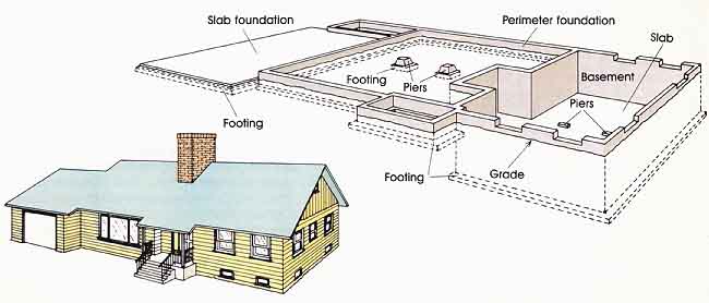
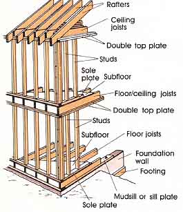
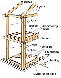
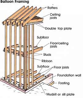
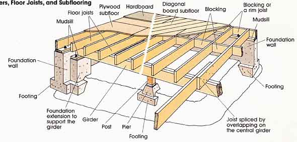
The Anatomy of a House In many ways the structure of your house is like the structure of your body. The skeletal frame provides strength and support. Hidden within the frame are such essentials as electrical, plumbing, and heating systems. The ex posed surfaces of the frame and systems are protected by various skins, such as roofing, siding, and wall coverings. Let’s inspect the anatomy of a typical house from the ground up. Study the illustrations as you go to visualize how everything fits together. The Foundation Most homes rest on concrete footings that transfer the weight of the house to undisturbed soil beneath the frost line. Above the footings is a foundation wall, which elevates the house above the ground to prevent decay and damage from moisture and insects, especially termites. If your home has no basement or crawl space, the foundation and footings are generally poured together in a single concrete slab. The Structural Framework The wooden framework above the foundation forms the skeleton of your house. Two basic types are used: post- and -beam construction and platform framing. If the type of framing in your house isn’t evident from the interior, you will be able to identify it in the attic, basement, or crawl space. Post-and-beam construction was the main type of building until the late nineteenth century, and it’s still popular in areas such as New England. Post-and-beam consists of a framework of vertical supports (posts) connected by horizontal spanning members (beams). The wooden timbers are large, perhaps 4 by 12 or 6 by 12 inches. Often the framework is exposed in the interior of the house and easy to identify. Walls between the wooden framework divide the interior space but aren’t an essential part of the structural system. Platform framing has been the predominant type of wood construction in the last 80 years or so. A variation called balloon framing is common in some older homes. The accompanying illustrations show the differences between balloon and platform framing. Instead of a few massive pieces that support a post-and-beam structure, platform framing employs many smaller pieces of lumber. Each floor is a platform or box that sits on top of the previous floor or platform. Most homes in the United States today were built with this method, which is the type of construction referred to throughout the rest of this guide. Even if the exterior of your home is brick or masonry veneer, the inner structure is probably wood that's platform-framed. The dimensions of wood used in platform framing have changed over the years. You should keep these slight differences in mind when you plan your remodeling. If you own an older home, for example the wood may have unplaned surfaces and a rough, almost fuzzy appearance. Those 2 by 4s may measure a full 2 by 4 inches, but in recent years lumber sizes have become smaller. Floors. If your home has a slab foundation, the concrete functions as the main platform for the house. If your home has a basement or crawl space, floor joists and subflooring provide a solid platform for holding up the rest of the house. The joists span the width of the basement and overlap over a main beam called a girder. Normal spacing between the joists is 16 inches from center to center, which is often abbreviated o.c., on center.
The type of subflooring nailed to the joists depends on the age of your house. If your home was built before 1950, it’s likely that boards laid across the joists, either diagonally or perpendicularly, form the subfloor. In post-1950 homes subflooring is either a single layer of ply wood or a double system of plywood and hardboard.
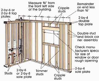
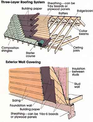
Walls. Both the exterior and interior walls of your home are framed with vertical studs nailed 16 inches on center between a bottom plate and two upper plates made from 2 by 4s. The framing is normally 2-by-4 lumber, but there are exceptions. For example, the first floor of a three-story house and newer homes built in cold climates may have 2-by-6 exterior walls. Also, the framing of one wall in your bathroom, called a wet wall, may be wider than 2 by 4 to accommodate large drain pipes. A word of caution: you may find odd spacing between the studs in your home. Don’t assume conventional spacing until you’ve actually checked the walls you’re going to work on. All exterior walls and some interior walls in your house are bearing walls. This means they are a principal support for the weight of the roof and floors above them. A bearing wall transfers its load to the ground through the foundation or through a girder and posts. The nonbearing or partition walls in your house do little but divide the interior space. They support only the weight of the materials nailed to their surfaces. In general. nonbearing walls can be easily removed without affecting the structural stability of your house. Bearing walls can't . To remove a bearing wall you must provide a permanent alternative means of support, such as a beam and posts. (For more information on how to identify and remove bearing and non-bearing walls, see this section.) Ceilings. The ceiling joists in your home provide a nailing surface for the finish ceiling and add stability to the framing by tying the exterior walls together. If your home has two stories or more, the ceiling joists for the lower levels are also the floor joists for the upper level. The framing procedure is simply repeated to complete another story, or platform. Once the top floor is reached, roof rafters are nailed in place, and the structural frame work of the house is complete. Exterior Surfaces The exterior surfaces of your house add stability to the structure and form a protective skin that covers the framework. It’s not necessary at this point to go into specific detail about how each material is applied. For now visualize your home’s roofing as three layers: wood sheathing or decking nailed to the rafters; building pa per; and a finishing roofing material such as shingles, shakes, tiles, or tar and gravel. In some cases the local building code determines which roofing finishes you can use. The exterior walls of your house can be summarized in a similar way: wood sheathing nailed to the outside of the studs, followed by a layer of building paper, and finally a finish siding material, such as wood, vinyl, aluminum, stucco, or brick veneer. Interior Walls and Ceilings Depending on the climate and the age of your house, the cavity between the exterior sheathing and interior wall surface may be filled with insulation. Fiberglass batts or blown-in loose fill are commonly used. Most interior walls and ceilings in your home are covered with one of three materials: lath and plaster, wallboard, or wood paneling. If your home was built before 1950. the walls and ceilings are probably lath and plaster Lath is thin strips of wood nailed directly to the studs and ceiling joists, over which several coats of plaster are applied. If your home was built after 1950, the walls and ceilings are probably panels of wallboard, a sandwich of 1/2-inch gypsum between two layers of heavy paper. Wallboard is also called drywall, gypsum-board, or Sheetrock, which is a trade name. The type of wallboard finish depends on the function and decor of the room. Your house may have some wallboard surfaces that are painted or wallpapered, while others are first covered with a skim coat of plaster and then finished.
Wood paneling can be individual boards or large panels. If your home has boards applied in a horizontal pattern, they are probably nailed directly to the studs. If the boards are applied vertically, a system of wood strips called furring is nailed to the studs first to provide a nailing surface for the boards. If the paneling is applied in 4-by-8-foot sheets, it’s made of plywood. Thin panels nailed directly to the studs tend to ripple and have a hollow sound. The usual method of application is to nail wallboard to the studs and then nail and glue on the paneling. The interior wall covering completes the basic structure of the house.
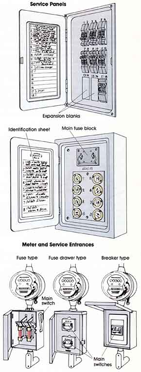
Mechanical Systems Intertwined within the structural framework of your house are three essential systems: electrical, plumbing, and heating. Even if you don’t plan to work with these systems directly, it’s difficult to do much remodeling with out exposing them somewhat. The Electrical System The electrical system in your house consists of a service entrance, where power enters the house, and various circuits composed of wires, out lets, and fixtures that distribute the power throughout the house. Safeguards are built into the system to prevent shocks, overheating of wires, and short circuits between wires that shouldn’t be touching each other. The main disconnect, a switching device that can shut off all power in the house, may be a pull lever, a fuse block that's pulled out, or a main circuit breaker that can be flipped off. It may be housed in a panel box of its own, but it's often in the same panel as the fuses or circuit breakers for all the house circuits. The main fuse block or circuit breaker has a limit to the electrical load it can carry. If that limit is exceeded, the breaker will automatically shut off electricity to the entire house, which prevents the entrance wires from overheating and causing a fire. This maximum current is called the service rating. Most homes today are wired for 100-, 150-, or 200-ampere service. However, older homes without updated wiring may have only 60- or even 30-amp service. The rating is determined by the size of the service-entrance wires and can't be in creased unless they are replaced with larger wires. Once power enters the house through the service entrance, it's distributed through the circuits originating in the service panel. You may have from 4 to 20 separate circuits in your house, each protected by its own fuse or circuit breaker located in the panel. When a particular circuit is overloaded, the fuse or breaker shuts off power to that circuit and prevents its wires from overheating. You should know which circuits serve each room in your house. Since this circuit wiring is concealed, you may never see it unless you crawl into the attic, open up a wall, or need to wire additional outlets and fixtures. The service panel itself must be properly grounded by connecting it with a No. 6 wire to a metal water pipe, a copper-clad rod driven deep into the ground, an ex posed end of foundation rebar, or a combination of the three. In turn, each outlet and fixture should be attached to a ground wire that leads back to the service-panel ground. When a short circuit or other malfunction occurs, the resulting surge of electrical power flows harmlessly through the grounding wire and to the ground, which is at zero volts. The surge also causes the fuse or circuit breaker to trip, shutting off the affected circuit. In addition to proper grounding, ground fault circuit interrupters (GFCI5) are now required in all bathroom, garage, and outdoor receptacles. These devices pre vent a person’s body from becoming a grounding path should a malfunction occur while handling equipment plugged into the receptacle. For a more complete discussion of how to do your own wiring, see our dedicated Home Electrical Guide.
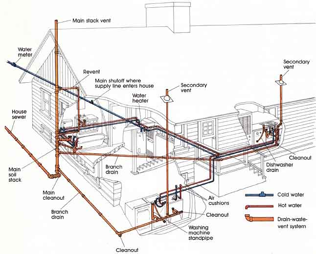
The plumbing system. Besides the actual fixtures, the plumbing in your home consists of two basic systems: a water supply system and a drain-waste-vent (DWV) sys tem. The supply system provides water under pressure; the DWV system carries away water and wastes by gravity, and gases by convection. • Water supply lines. A main or service line supplies your home with cold, fresh water. The main normally comes through a basement wall or lower-level utility area. It your home is connected to a municipal water system, the water enters under pressure and travels through a meter. In private supply systems, water is pumped from a well or cistern into a holding tank. Air pressure in the tank creates sufficient water pressure for household use. Once inside the house the main water line splits into smaller branch lines. One of these goes directly to your water heater. From there hot-water branch lines travel to fixtures that demand hot water, such as the kitchen sink and the bathroom washbasin, tub, and shower. Cold-water supply lines also split from the main into different branches. One branch, for example. may sup ply water to the kitchen sink, another may supply water to an upstairs bathroom, and a third branch may supply an outdoor sprinkler system. Shutoff valves, an essential part of your water supply system, are very helpful in remodeling. A main shutoff valve, located where the main line enters the house, will turn off the water to the entire house. Each branch run should also have a shutoff valve, as well as the inlet line to the water heater. Fixture supply valves beneath wash- basins and toilets allow you to turn off the water to a particular fixture whenever necessary. • The DWV system. The drain-waste-vent system depends on gravity to carry wastes away, which means the direction and pitch of the pipes is critical. A drain pipe must slope downward 1/4 inch for every foot of horizontal run—otherwise water would stand in the pipes and sludge would build up.
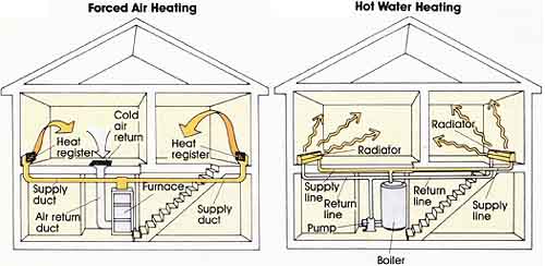
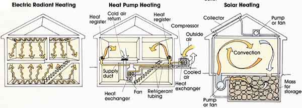
Each fixture or drain in the house must have a trap beneath it, a U-shaped dip in the line that remains filled with water. The trap seals off the waste line and prevents noxious fumes as well as vermin from entering the house. Cleanout fittings allow access to each drain in case of plugging. Drain lines from each trap carry the wastes to a vertical pipe called a soil stack. The stack connects to the main house drain, which empties into a private septic tank or municipal sewage system. Vent pipes are an integral part of the DWV system. These pipes rise vertically from the drain lines and connect to one or more vent stacks that exit through the roof of the house. The vents bring fresh air into the waste system and carry away unpleasant or dangerous gases that may accumulate. Both the supply and DWV lines run within the walls and floors of the house. Holes are simply drilled through studs, joists, and plates wherever the pipes need to run. Code limitations on the size of notches and holes prevent the structural strength of the framework from being weakened. In some instances cuts in the studs and joists must be reinforced with metal plates to protect the integrity of the framing. • Gas lines. Your remodeling project may involve altering gas lines. Although some homeowners are able to do this work themselves, with proper permits, you will probably need professional help. Among other things, gas lines must be sized carefully to ensure a steady flow of gas under pressure to the farthest fixtures. Also, only certain kinds of pipe, fittings, and joint compounds are allowed for gas lines. • Septic systems. For some remodelers, adding a bath room or building a room addition may mean enlarging a septic system or even relocating it. This will involve installing a septic tank of the correct size, providing a vent (if needed), and laying an adequate array of leach lines. You should be familiar with the type and age of your system. For more information about plumbing projects, see our Guide to Basic Plumbing Techniques. The heating system. Unlike electrical and plumbing systems, which are essentially the same everywhere, heating systems vary widely in the type of energy they use and the means of distributing it. Some homes rely on space heaters—woodstoves, fireplaces, portable heaters, or wall or floor heaters, More commonly one of four types of central heating systems is in use, with solar alter natives becoming more prevalent in certain areas. • Forced air. This is the most common central heating system. The heat producer is a furnace that burns oil, gas, wood, or coal inside a combustion chamber. Waste gases are vented outside through a metal flue and masonry chimney. When the air surrounding the combustion chamber gets hot, it’s distributed through the house in a network of ducts. In a slab foundation the ductwork is generally embedded in the concrete. With a crawl space or full basement, sheet metal ducts run underneath and between the floor joists. In a two-story house the upper-level ducts run up the walls, hidden between studs or inside closets. The furnace is turned on and of f automatically by a thermostat, but the heat supply to each room can also be controlled manually. Dampers inside the ducts and at each register open and close to regulate the incoming warm air. • Hot water. In a hot-water (also called hydronic) sys tem, the furnace is a boiler fueled by oil, gas, electricity, or coal. The boiler heats water to about 200°F, and small pipes (½ to 1 inch) made of galvanized steel or copper distribute the hot water to each room of the house. If steam and cast-iron radiators are used, the system works with gravity. Pressure from the boiler and lighter density cause the steam to rise naturally within the pipes. Once it circulates through the radiator and condenses. the cooled water returns via the same pipe to the boiler, where the cycle begins again. In a modern hot-water system, water is forced through the pipes by a circulating pump. Like a plumbing system, the hydronic system has a main supply line that branches from the boiler into two or more supply runs, or zones. Alter serving each room, the cooled water is cycled back to the boiler by a return line. Separate temperature controls are provided in different parts of the house. The heat is dissipated into the room by baseboard heaters, which fit unobtrusively along the floor, most of ten along the outside wall of the house. Generally they’re only 8 to 10 inches high and 2 to 3 inches deep. • Electric radiant. Homes equipped with electric radiant heat have no furnace, ducts, flue, or chimney. The source of heat is electricity flowing through resistance wiring, which can be installed in the ceiling between two layers of wallboard or beneath the plaster. In mild climates the wiring is often located in the floor, embedded in the concrete slab. If the wiring isn't in the floor or ceiling, baseboard panels are mounted along the floor. Some electric baseboards use only resistance wiring to heat the room. Others use electricity to heat water permanently sealed in copper tubing. Each heater is a self-contained hydronic system that needs no plumbing or separate water supply. Air drawn from the floor passes over the fins of the tubing and circulates upward to warm the room. The hot water continues to provide heat after the electricity is turned off by a thermostat. • Heat pump. The heat pump is a combination heating and cooling system that operates like a central air conditioner, with a reverse cycle for heating. Electricity is the energy source. In the summer the system withdraws heat from inside the house and dispels it outdoors. In the winter it extracts heat from the outside air and pumps it inside. The air is distributed through the house via sheet- metal ducts just like a forced-air system. If the temperature drops below a certain level, auxiliary electric resistance heaters kick in to provide supplementary heat. • Solar. Until recently heating systems were usually chosen on the basis of output of BTUs, fuel cost, and convenience of installation, Skyrocketing energy costs have caused homeowners, builders, and architects to consider heating systems from the standpoint of energy efficiency as well. Furthermore, they aren't only concerned with how efficiently the heat is produced, but with how well the home retains it. Conservation measures like insulation, weatherstripping, and caulking are at least as important as installing an adequate heating system. The most efficient and innovative designs are now tapping direct sunlight as the major heat contributor. The means of collecting it can be as simple as increasing the number of south-facing windows or aft aching a hot- air collector to a south wall. Or it can be as complex as a complete redesign of the home to incorporate additional south glazing, substantial amounts of heavy mass, and a floor design that creates an optimum flow of natural air currents. In all cases solar heating designs re quire a home site with continuous exposure to the sun during the cold winter months for at least the four hours from 10 am to 2 pm. For more information on assessing energy efficiency along with your other home needs, see our web site dedicated to Energy-Saving Projects for the Home.
Central Heating Systems
|
| HOME | Prev: Considering the Basics | Next: |