IS A PICTURE IS WORTH A MILLION DOLLARS?
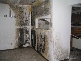
above: Moisture can lead to dangerous mold!
A picture used to be worth a 1,000 words. With the recent increase in litigation related to mold and mildew, we believe that a good picture (photo) may be worth millions. A lawsuit on a commercial building can exceed $10 million for remedial work alone. If the architect can show that he or she provided good design and proven details that have successfully prevented water intrusion and mold in similar projects, then the courts may choose not to find fault with the architect. Imagine that the contractor has documented evidence that the building was well built, with better-than-industry-standard water test results for the roof, window, and wall systems, as well as the building air conditioning system. Might the courts have a hard time proving either of them at fault and perhaps find someone else to pay the price? What could be better than that? How about avoiding the problems and lawsuits altogether. Well-conceived design and clearly communicated architectural detailing can lead to fewer problems in building construction, operation, and maintenance.
Today, more developers and builders are willing to make the commitment of time and money required to prevent indoor environmental quality problems, such as mold and mildew, through proper application of materials in the proper sequences.
At the same time, labor and materials costs are escalating. In some areas, such as China and the southern United States , buildings are going up at a record pace. This increased demand is causing an infusion of workers with little or no training in the building trades in these areas. To make matters more challenging, many workers don't speak the same language as their supervisors or the language in which the drawings were done. This places a large burden on leadership in design, construction, and development firms. In a business where thousands of decisions are made for a single building and where one missed membrane or improper lap can lead to millions of dollars worth of problems years later, what can we all do? Throughout this illustrated guide, we will discuss the importance of teamwork and cooperation among all the participants in the building process. We have found that the best recipe for success is a series of sound decisions made throughout the processes of design and construction that keep in mind the basic principles contained in this guide using gravity, geometry, and technology (in that order of importance, please).
Regardless of the style of the building, the budget, or even the location, there are common ways that we all design a building envelope. Gravity always will be acting in the same general direction. We all must use the force of gravity to help our building envelopes perform as intended. Whether we are talking about resisting live and dead loads, stack effect, temperature and pressure of gases or raindrops falling on a roof, gravity is the single most constant physical force that acts on all buildings. Gravity, therefore, is the first thing to consider as we design our buildings. This applies at all levels from the location of the building on the site to the way the ground slopes away from the front door and walls (). Gravity affects the slope of the roof, the direction and lapping of materials, and much more.
Slope grades away from the building.
Flashing geometry to prevent water intrusion.
[[ Concrete Tilt Wall Formed Reveal or Reglet Drive Wedges, to Secure in Slot Backer Rod and Sealant Counter Flashing Receiver Metal Base Ply Membrane Transition Flashing "Z" Closure (Fastened and Set in Sealant, or Soldered as Material Permits) Architectural Metal Roofing Panel]]
Other physical forces are less consistent than gravity, such as sun and wind, making it more difficult to fully consider them through design and construction. Throughout this guide, we talk about the benefits of using geometry and applied technologies to combat the forces of the natural environment. We explain the relationship between the geometry of flashings and their ability to keep water out of joints or penetrations (see Diagrm. 2-2). We discuss ways and means to take advantage of gravity and geometry to reduce the force of wind driven water and ultimately to prevent liquid water from defeating the building envelope. Gravity and geometry are the primary forces to be considered for the slope of the roof and selection of roofing materials such as modified bitumen or shingles. In addition, these forces are instrumental in determining the lengths of laps in applied waterproof membranes such as fiberglass or felt underlayment, as well as heights of skylight flashings and door thresholds.
We introduce the premise of relying on available technologies as a final line of defense against water intrusion, vapor migration, and condensation. By technology, we mean powered systems, such as ventilation or air-conditioning, and chemically engineered systems, such as self-adhesive membranes, backer rod, and sealants. It is our belief that technology needs to play a significant but tertiary role in building envelope performance as it relies upon variables such as the reliance on electricity, maintenance, repair and replacement, or proper operation for it to perform its intended function. We recommend strongly that sealants are not relied on as the only line of defense against water intrusion! We are calling this manuscript an illustrated guide for many reasons. Without pictures, it would take too many words. With pictures, it crosses the language barrier. With clear pictures, there is reduced possibility for misinterpretation by the person in the field. One can see the location of each of the critical components in a successful cavity wall system. We have seen the benefit of large-scale details in practice and of holistic coordination of trades in the field. Our clients have benefited from reduced numbers of change orders during construction and in significant reductions in operation and maintenance costs over time.
We believe that by following our guide, you will be able to apply a systematic approach to any family of building-type decisions as they apply to building envelope performance. Included in the guide, you will find numerous examples of plan and section details that have been time tested to provide good levels of water and vapor protection against the elements.
We also provide some examples of good and bad details for the same condition so that you can all see the difference a small change can make. While no one in the world is perfect, we have found that if all the people in the chain do their best to apply sound practices, the end result will have few significant failures. By working together with the developer, designer, contractor, and installer, all working toward the same stated goal (and at the same time learning from each other), we can all continue to build better and better buildings for centuries to come.
The decisions made in relation to the building envelope will determine how well the systems perform over time even more than how the building will appear when finished. As designers and builders, we must make informed decisions that lead to the creation of a built environment that will stand the test of time and lead to long-lasting relationships with developers and clients of all kinds. Our most important clients are the public who live in and around our buildings.
MOLD -- HOW TO STOP ITS GROWTH
We need to design and construct buildings to prevent the intrusion of water.
Now we know that this sounds like a very simple statement, one we presume that at least most of you will agree with. But all too often water has created problems in the past. As you get farther into this guide, we will discuss just what those problems are and what caused them. By studying causes of past problems, we should be able to better prevent them in the future.
As most of you know, water is made from two of our most common elements, hydrogen and oxygen. Water is sometimes referred to as the universal solvent due to the wide variety of materials that can be dissolved in water. As it relates to the topic of this guide, water is also necessary for survival and growth of nearly every life form on earth. This certainly holds true for mold.
What is mold? Mold is a single-celled organism that comes from spores. Mold spores are very small and light. Their two most common means of movement are by hitchhiking or by becoming airborne. The spores can land on surfaces during construction or may be carried in by wind, on animal hair or human clothing. They can lie dormant for a long period of time, waiting for an opportunity to grow. They thrive in the same general temperature range as humans, from about 40 to 100ºF. Only in the presence of oxygen, nutrients, and moisture can most reproduce.
Spores rely on moisture to dissolve food to fuel their growth and reproduction.
If the surfaces they come to rest on don't provide food, then they can't grow.
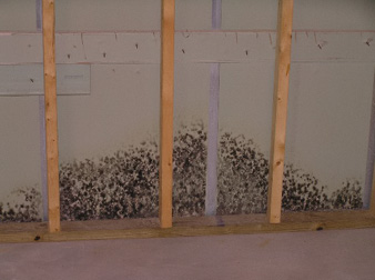
Spores can lie dormant for a long time. In the presence of food and water, the spores will germinate, producing filaments called hyphae (see Diagrm. 2-4). If the hyphae have a sustained source of food and moisture (typically for more than 48 hours), they will continue to grow and change appearance. As hyphae grow, they extend their filaments in all directions to form a protective layer (see Diagrm. 2-5).
A portion of the hyphae root into the surface on which the spore came to rest, whereas others form a protective shield around them. This works to keep the roots moist, even if the air around them dries out. In the final stage, the mold grows a kind of bloom, called conidia (see Diagrm. 2-6). When the conidia reach a certain point, they generate and release spores into the surrounding air.
We can't live in an environment without water or oxygen. What we can do is try to limit the concentration of spores, limit the amount of nutrients in and on surfaces where spores may come to rest, and limit the moisture in contact with those surfaces.
Mold spores extend hyphae.
Mold is a single-celled organism.
As hyphae grow, they form a protective layer.
Final stage of growth, release of new spores.
Limiting the spores
Spores come into our built environments during and after construction. The best way to limit spores during construction is to keep things under protective cover until they are installed and the building air-conditioning system is on. Stored materials, especially those containing organic materials such as cement, wood, and paper products, should be kept clean and dry. In addition, we can wipe exposed materials often and vacuum floors and other horizontal surfaces. Before hanging drywall, we can wipe all exposed surfaces with a dilute solution of chlorinated water and let them dry fully. Before assembling ductwork sections, we can clean the surfaces, especially those that will be in the airstream.
After the building is dried in, we can continue to try to minimize the admittance of spores. Keep doors and windows closed. Use the leeward doors to enter the building. Use garages or warehouses to store materials. Wipe materials before bringing them in. Use walk mats. Try to keep pets and other animals from the building. Clear away brush from the building proximity. Use construction filters on return and outside air makeup. Change these filters often.
Make a conscious effort to keep the building clean during construction. At least once a week (Friday is a great time for this activity), clean the entire project using a vacuum rather than sweeping. Brooms raise the dust, letting air currents move the spores to new surfaces. If you must sweep, use the specially formulated sweeping compounds that minimize airborne dust and pollutants.
Limiting nutrients
This begins with specifying the right materials. Designers may have to spend more time researching and writing new materials into our specifications, but the results are worth it. A good rule of thumb is that if it ever grew, it probably still contains nutrients. If it's open-celled, it can absorb nutrients from the surroundings, such as dirt and dust, and it may fuel growth. Products that contain cotton, jute, paper, or wood provide nutrients. Many synthetic materials, such as nylon, fiberglass, as well as glass, and metal, don't provide fuel for growth. Some wood is less conducive to mold growth than others. If wood is used, we must consider how to protect it, such as using paint or other coatings that effectively prevent spores from being fueled. Manufacturers provide material safety data sheets (MSDSs) and material product data sheets to inform users of the contents of materials (see Diagrm. 2-7). Something that's high in volatile organic compounds (VOCs) would be something to avoid. Most organic compounds are acceptable forms of nutrients for mold growth. Keep food and drinks out of the building envelope. Never permit waste products to remain in wall framing.
During construction, workers can help to minimize nutrients introduced into the building by keeping materials covered when stored, uncovering them when inside, and covering work. Covering work in place can keep dust and dirt from settling on it. Sometimes work from other trades cause small particles to be carried by the air moving inside the building, bringing sawdust, drywall compound, or paint with it.
Sawdust, spray fireproofing, and most paints make great food for spores.
Limiting moisture
Moisture must be limited at every phase of construction. How many times have you seen building materials delivered long before they are needed? And how many times have you seen stacks of lumber or cubes of masonry products left uncovered during a rainstorm? Until recently, we never could put our finger on exactly why it bothered us so. Not only does uncovered material have a good chance of getting dirty (see above), but in most climates it's probably going to get wet. Yes, masonry should not be "dry" when set, but neither should it get wet a week or a month before it's used.
Block that gets wet by the rain or, worse, sits in a big pond in the yard after a rainstorm has a potential for growing spores into mold before you even put the roof on. We recommend that you try hard to keep the masonry as dry as possible until an hour or two before it gets laid and then wet it with clean water that you know has no dirt or spores in it. The same goes for exterior plywood or treated-wood products. They should never be allowed to get wet, and if they do, they should be dried thoroughly. We don't mean that it has to be stored in a dehumidified warehouse, although a warehouse is a great idea. Many clients will pay for materials up front in order to limit inflation and reduce the risk of potential shortages. If it rains on the slab, sweep and shop vacuum it off before placing wood or concrete walls. Limit the moisture content. Protect work from getting wet after installation. Design and construct buildings so as to limit rain's impact on completed portions of the work. If stored materials do get wet, dry them as soon as practical (preferably less than 24 hours).
There are three different ways water moves in walls: gravity, pressure, and capillary action. Gravity is a constant force, one that we can count on when we design details that use it to our advantage in preventing water intrusion. By pressure, we mean forces other than gravity, such as wind. Wind-driven water can strike the exterior walls and reflect at any angle. Another force is momentum, the tendency for any mass in motion to remain in motion until acted on by another force. The third way water moves in walls is by capillary action, by wicking through porous materials.
This occurs as a result of differences in saturation, temperature, or pressure.
Where does the water come from? Most water comes from rain, but it can result from condensation on cool surfaces, from leaks in pipes, from surface drainage, from subterranean infiltration or from use of water in everyday activities.
Showers, cooking, mopping hard surfaces, carpet cleaning, and pressure washing are the most common activities with water leakage potential. Condensation is caused by vapor (water molecules in gaseous air) changing temperature and /or pressure to a point where it changes phase from vapor into liquid water. The temperature is called the dew point, the point at which gaseous water changes to liquid water. Most of us know that warm air holds more water molecules than cool air for the same volume of air. I'm sure we all understand the dynamic temperature ranges that exist in an annual cycle of seasons. But I'm not sure how many of us are aware of the many different temperatures that exist in the cross sections of a typical wall or in different areas of the same room.
By use of thermography, we can find surfaces ranging from about 45ºF at supply grilles to more than 90ºF on glass. Why is this important? Because often the temperatures in the exterior wall are within a few degrees of the dew point. The location and R value of the insulation in the wall can be as important to the prevention of problematic condensation in our walls as is the quality or size of the air-conditioning system. When condensation takes place within the wall cavity, it can lead to mold growth, as discussed previously. By carefully considering inside and outside temperatures, as well as proper placement of insulation and vapor barriers in the wall systems, we can minimize the potential problems. As discussed earlier, some materials are better sources of nourishment for spores than others. We need to plan the location where condensation takes place in the wall to be on a surface where there is no food to sustain growth.
Then we need to create a way for accumulated condensation to drain out of the walls without causing damage or promoting fungal growth.
PUTTING IT ALL TOGETHER
A good first step is to grade the site so that water sheet flows away from the building pad. If an area is designated for future stored materials, build it up and slope adjacent earth away. Put enough money in the bid for labor and material to cover this work more than once. Assign a senior staff person the responsibility of keeping materials dry. Work to dry in the building as soon as practical.
Whether you are working on a small residence or a 20-story commercial building, it's wise to dry-in the shell as soon as possible (certainly prior to installing paper-backed drywall or kraft-backed insulation). Many builders have switched to paperless glass-mat gypsum drywall for use as a wall sheathing for installation before air is on for just these reasons. These materials don't contain fuel for growth. If plywood is installed, it needs to be protected before the first dew or rain. Get the building dried in and air conditioning on before installing products containing organic materials, whenever possible.
For designers and builders to reduce the number of mold and mildew cases each year, we need to limit the number of spores in or on our construction projects.
We must limit fuel and moisture that enable spores to mature. By limiting organics inside the membrane, we will reduce fuel for mold growth. This can be accomplished by material specification and protection. By then reducing water, vapor, and condensation, we can limit future problems.
We could foresee a heating, ventilation, and air-conditioning (HVAC) system in the future with a series of integrated temperature, humidity, CO2 , and differential pressure sensors all networked into a central processor. This is within the capabilities of today's building automation systems. The software would man age a series of variable air volume supply and exhaust systems. In this way, we could sense local differential pressure conditions at multiple points around the perimeter and balance the entire building's outside air and exhaust systems to maintain a desired differential pressure at the skin in the most cost-effective way.
The differential pressure sensor function would assure us that all the pressure driven water vapors are always moving from the inside out. If we have stopped wind-driven and differential pressure-driven vapor transmission, we will in most cases have successfully limited indoor mold growth resulting from vapors. The humidistats placed in wall and roof cavities could sense when moisture is building up in an area of the building envelope. This could serve as an early-warning system that could let maintenance personnel know of changing conditions. If this level of feedback were available, maintenance staff might learn of a wall that needs repainting, sealant that's failing, or a roof membrane that has developed a leak long before the problem spreads.
So now that we have discussed the growth cycle, you can see the importance of moisture (water) to the process. Later we will discuss how to minimize spores in the built environment. More important, let us now focus on how to keep the water out of the building. How does the water get into the building? The different ways can be broken down into four main categories: (1) bulk water (in the liquid state), (2) air-transported moisture (typically water vapor), (3) vapor transmission (through materials that are permeable), and (4) condensation formation. Of the four, the most important to stop is liquid water.
A small void in the building envelope can let in more water than leaving out half the vapor barrier. So how do we best stop water? We have to take into account winter and summer thermoclines. We recently learned of an architect being sued for condensation that was forming on the interior face of exterior walls during winter months in south central Florida.
The project was designed and built as low-income housing. Stucco exterior concrete masonry unit (CMU) walls had metal furring with 3/4 inch of insulation and drywall. Kitchens, laundry, and bathroom walls had been painted with enamel. With the increase in energy costs, occupants had reduced heating set points or turned off systems to save money.
You can imagine a number of scenarios in which the occupants contributed to the conditions that led to mold growth. Perhaps there was a cold night, with temperatures in the thirties or lower. The heat was turned off, and lots of blankets were used to sleep. Due to the thermal mass of the block, temperatures never got below 50ºF in the house. Around 9 A.M., the occupants arose and took a long, hot shower to warm up. Imagine that the area vent fans were not used; perhaps they were too noisy. The room air temperature could get up to the 85ºF and 100 percent relative humidity (RH). Moisture would then form on every cool surface in the room, potentially saturating the paper facing on the drywall.
SELECTING THE RIGHT CLASS OF CONSTRUCTION
In areas such as Florida , where there is a high probability of high winds and rain exposure, it's recommended that we use a rain screen wall referred to as a cavity wall system. In this way, we have a dedicated drainage plane for water to drain down and out, as well as a pathway for removal of warm air vapors up and out at the top. Another advantage is that the break between the two parts of the wall serves as a thermal break for conductive materials and reduces the potential migration of moisture by capillary action or vapor diffusion. The big challenge in design and construction of a cavity drainage scheme is in preventing pathways for moisture to flank, penetrate, or bypass the drainage cavity membrane.
Depending on project budgets, preferred materials, and available skilled labor, there are many ways to achieve a good wall system. Every well-designed wall will take advantage of the inherent physical properties of the materials used. As designers, we have to balance performance with budget, client's preferences, and in some cases prejudice based on ignorance. It is our duty to do our best to ensure that an acceptable level of performance can be achieved. A cavity wall can use many layers of defense against bulk water intrusion, starting with the outside face of the wall. The outermost material is the one exposed to sun, wind, and rain, as well as dirt and ultra violet rays. For these reasons, vinyl siding, stucco, and exterior insulation and finish systems (EIFSs) are very popular. Each of them has different initial, operating, and maintenance costs associated with their use. Each is resistant to ultraviolet (UV) radiation and is durable. Each also has inherent limitations, and we must take care to design and specify all the right component parts to enable the finished wall systems to keep out moisture and limit condensation.
Several experts on the subject have voiced their opinions on wall types related to rainfall. We have created our own table, based upon a compilation of others, mixed with our own experience. In it, we recommend the use of rain screen (cavity) walls wherever rainfall exceeds 40 inches per year.
We recommend that walls designed for use in residential, commercial, and other occupied and conditioned spaces in Florida and most southern states within 150 miles of the coast be based upon a cavity wall system. The 2005 Florida Building Code (FBC) requires in stucco on frame walls the use of, at a minimum, a drainage plane. The drainage plane is created by the use of bond-breaker materials between the outer coatings or finish material and the insulation layer. What is the difference, and why do we use one or the other? In a cavity wall system, there are two distinct parts separated by an airspace.
The airspace can be quite small but functions better if it's at least 1 1/2 or 2 inches in width. The cavity is designed to provide a pathway for liquid water to drain out of the wall system. Similar to cavity wall construction, the drainage plane has a very small pathway for water to drain down and out of the wall. A drainage plane can be created by the use of Tyvek stucco wrap or one of several other three-dimensional membranes that because of their irregular surfaces make space between the bumps for drainage to occur. These typically get installed right up against building paper, felts or other vapor retarders.
Recommended wall types for different rainfall averages Diagrm. 2-8 Small drainage void between membranes.
At some points, the two materials are touching, and at others, there is a small (usually less than 1/16 inch) space between membranes.
This still will allow liquid water transmission by capillary action and vapor transmission by permeability. It also reduces the thermal break between materials. Two layers in close proximity still may permit both sides of the drainage plane to be touching, so it can't perform as well as the cavity wall system. Another consideration is that if the two membranes are installed one on top of the other (touching), then what happens at joints or laps? The extra thickness of material can block the drainage pathway. There is no room for construction tolerances or laps in materials, etc. This equates to an increase in potential liability for the owner, developer, builder, and designer. Liability is bad. Although the codes are becoming more stringent by requiring two barriers behind stucco on frame walls, we don't recommend that you rely on building-code minimums as your recommendation in design. We believe that you need to do more than the minimum, and we believe that you must.
Yes, a cavity wall can have a higher initial cost, but if it's done right, not only can it reduce the risk of mold and mildew, but it also can pay for itself as a result of better insulation values and reduced energy costs. If we work hard and smart, the payback can be as few as 10 years but in every case should result in longer lasting, better indoor conditions for people using the built environment. In warm climates, the interior face of the drainage cavity should be the place where water and vapor transmission is at a minimum. This is also the point where you want condensation to take place. Regardless of the wall system chosen, the interior face of the cavity should have the lowest permeability of all wall materials (see Diagrm. 2-9). We believe that this is the best location for the moisture barrier. You want to stop bulk water at the outside face of the exterior walls. You then want to stop air infiltration to minimize moisture in the wall cavity period. If these two steps are done properly and you don't screw up something else, the building should not have mold and mildew problems. Yes, we said it. Stop liquid water and stop wind, and you've effectively reduced the potential for mold in your buildings. Do we think that this is enough? No! Lowest permeability on inside face of cavity wall.
The most important consideration in preventing moisture in the building environment is stopping liquid water. This usually relies on a series of parts, each designed and installed to perform a key functional role. We have to resolve all the obvious natural forces such as sun and rain, as well as other forces such as expansion and abuse from people, plants, and animals. We have to stop water from all six directions. The roof system must stop water from above, the walls from the sides, and the floor system from below. We typically use different products for these applications. You would not expect to use visqueen for a roof or shingles for a basement. Visqueen below grade or below crawl space floor insulation if properly installed is good at preventing moisture from reducing thermal performance of batt insulation.
Visqueen does not resist punctures or tears well, so it can't be relied on as a roofing system, at least not without protection. This is why we rely on very hard materials such as ceramic roof tile, metal, or concrete for long-lasting roofing materials exposed to the weather. Those products can be relied on to resist UV light without degradation, as well as punctures from small branches or wind-blown objects. Underneath these hard materials, we use more flexible products to stop the water from permeating the system. We rely on gravity to drain the water down and away from our occupied spaces. Many roof underlayments are hygroscopic, which means that they absorb some of the water they come in contact with. These products release that moisture back to the atmosphere after the rain stops.
You may have seen steam rising up from a hot roof after the rain stops on a hot summer day. In hurricanes, we often have rains lasting for several days. In those cases, the underlayment stays saturated and can begin to transmit moisture onto the sheathings below. Many of our roof sheathings are quite absorbent and permit the transmission of moisture through them as well. Most are wood products, which provide food for mold growth.
In walls, we have much the same situation. When wind-driven rain hits the exterior skin of our buildings, even on a porous material such as stucco, on average, only about 1 percent of the water enters the wall through the wetted surface. One small hole in the skin can let in more water than 1,000 square feet of exterior wall sheathing, even assuming that no water-resistive barrier is present. Thus we try to design the wall system so that it can be constructed to have no voids or holes. We typically use a hard material to protect a more flexible membrane. Again, we rely on gravity to drain surface water down and away from our occupied spaces. We use a broad variety of outer skins, ranging from wood to plastic/vinyl, to brick, to stucco, or to plaster.
An exception to this is the use of exterior concrete block as a skin. Some waterproofing consultants tell us to design around breathable block and breathable paints, whereas others say to use the best elastomeric paint at the face. Manufacturers are making special blocks that don't wick water and special foam inserts that allow for vertical drainage in at least part of the wall system. So how do we know which one to use and when? Gravity first.
Positive and negative window jamb detailing. Positive Detail Might Use Applied Trim to Block the Path at the Jamb; Negative Detail Relies Upon Sealant at the Jamb
Example of positive roof detail.
GRAVITY, GEOMETRY, TECHNOLOGY
We recommend that you try to use the following simple rule: Gravity first, geometry second, and then technology. Think of the way time-tested installations work. We like to think of lap siding and lapped shingles as a way to explain the first two parts, gravity and geometry. We know to lap the siding, shingles, or membranes from the bottom up. This promotes the use of gravity (see Diagrm. 2-10), to have water rolling down the materials, and prevents water from getting behind the membranes at a lap. This same principle should be carried over into above grade detailing at every condition.
The geometry part comes in to play when we consider the physical fact that water (or any mass) tends to maintain direction and velocity unless and until it's acted on by another force. Thus every time water droplets change direction, shape, or size as a result of our building component geometry, they lose energy. We like to place permanent materials in the path of wind-driven water to prevent their easy entry.
If you walk up to a wall before sealants are installed and you can see light through a void, this is an easy pathway for wind-driven rain.
This is the main reason that we prefer positive detailing to negative detailing.
We don't recommend anyone rely solely upon sealant to stop air and water intrusion over time.
Geometry second.
Designs should avoid reliance upon sealant.
You can see the difference easily in the two examples provided.
The geometry of the positive example clearly provides a more difficult to defeat condition for wind-driven rain.
Similarly, in the Positive roof edge example one can easily see more pieces of material blocking the path for wind-driven rain to enter the building envelope. In the Negative example, materials are abut ting instead of overlapping the joints with the next successive layer.
Flashings rely on gravity and geometry. We don't have to extend our flashings more than about 8 or 10 inches vertically behind wall finishes because water droplets hardly ever climb more than that before they slow to where gravity pulls them down and away.
Example of negative roof detail. [Expressed Posts Exposed Tails Fascia Beams Planks Galv. V-Crimp Roofing with Exposed Fasteners on Top] Improved slab edge water stop.
A well-designed and well-installed flashing will go one step farther and stop even hurricane-force winds from driving water droplets beyond the vertical height of the bent metal. This can be achieved by use of another 180-degree bend at the top, this one to redirect water back down (see Diagrm. 2-16). Geometry also relates to the seaming and closure at joints in horizontal and vertical materials. We must minimize the potential for water to get around the flashing, whether we weld, rivet, caulk, or bend laps in flashings. This is using technology to improve geometry. Technology also comes in when we add a bead of sealant to the top of this flashing. This will reduce the potential for even the most energetic droplets from getting past, above, or behind the flashing.
Adding roofing sealant to a row of starter shingles could be considered adding technology to geometry. The nails and sealants ensure that the geometry will stay in place to take advantage of gravity.
Air pressure control
After we stop liquid water, we have to minimize water vapor intrusion next. Air barriers play the most important role in reducing water vapor infiltration in our buildings. We can calculate the number of grains of water that result from the various kinds of transmission modes to reinforce this statement, but experts assure us that vapor transported by air currents introduces between 100 and 200 times the amount of moisture into our buildings than occurs from vapor diffusion through materials. Airborne water vapor accounts for more than 98 percent of all the vapor movement through the building envelope. The important message here is that we must work diligently to stop leaks in the air barrier at the perimeter.
A certain amount of outside air is necessary to maintain a healthy indoor environment. There are several ways to determine design values for outside air, just as there are ways to achieve the design values. The old American Society of Heating, Refrigerating, and Air-Conditioning Engineering (ASHRAE) standard was 15 to 35 cubic feet per minute (cfm) per person depending on their levels of activity. Some designers prefer to use CO2 sensors to maintain acceptable levels of CO2 in the air and connect the sensor output to variable outside air makeup systems. Both systems have their advantages and disadvantages.
We would rather have too much outside air than just barely enough, but we sometimes must consider how much we can afford to bring in. It costs money to provide more than we need because outside air is usually dehumidified and cooled prior to introduction into the building's occupied spaces (summer cooling, cooling conditions). We could foresee a system in the future with a series of integrated differential pressure sensors, all networked into a series of variable air volume supply systems. In this way, we could sense local differential pressures at multiple points around the perimeter and balance the entire building's outside air and exhaust systems to maintain desired differential pressures at the skin (air infiltration barrier, or AIB). This would assure us that all the pressure-driven water vapors always were moving from the inside out. It is our belief that pressure-driven vapors carry far more grains per cubic foot than vapors moved as a result of differential temperatures (at the same pressure). If we have stopped wind-driven and differential-pressure-driven vapor transmission, we will in most cases have limited indoor mold growth as a result of moisture from vapors successfully.
After vapors are introduced, we need to prevent their movement through the building. Air (and airborne water vapors) has three principal means for movement within a building. They are wind pressure, stack pressure, and differential pres sure. Wind pressures create different directions of flow. To simplify things, wind pressure is positive on the windward side and negative on the leeward side of walls and roof surfaces.
Stack pressures are created by gravity, and by the tendency for warm air to rise and , as it rises to the top, create a relative negative pressure behind it. We need to try to seal vertical wall and horizontal ceiling cavities at floor levels to reduce transmission resulting from stack pressures. Differential pressures typically are caused by the air-conditioning and ventilation systems, ideally creating a positive pressure all over the building exterior skin just strong enough to over come the wind- or stack-generated negative pressures in order to maintain constant flow (from pressure) from in to out. This will help to keep out new spores and reduce outside air infiltration.
Air barriers are also important so that we can maintain positive pressure in our buildings with the least amount of waste energy. In buildings that are mechanically ventilated, it's important to have the best possible airtight enclosure.
This can be achieved by having a continuous and well-sealed air infiltration barrier (AIB) constructed from materials with low infiltration rates (high infiltration resistance).
Pressures acting on vapors.
Water vapor transmission reduction
Let us now focus on stopping the transmission of water vapor by means other than air movement. The least permeable materials, such as sheet metal, rubber sheets, and polyethylene film, all have a permeability rating of 0.1 or less.
These are classified as vapor-impermeable, or vapor barriers. Little, if any, vapor passes through them. Vapor retarders can be grouped into three basic categories based on how permeable they are. A permeability rating is based on the amount of water in grams that passes through a square foot of sample material at an assumed standard pressure differential.
The next classification is referred to as semi impermeable, ranging in permeability rating from 0.1 to 1.0. These materials include vinyl wall coverings, oil-based paints, stucco over building paper with glued oriented strand board (OSB), and unfaced polystyrene sheathing about 1 inch thick. Semi-permeable materials include unfaced expanded polystyrene (EPS) board, 30-pound felt, latex paints, and typical plywood and OSB sheathing. They range in permeability from 1 to 10.
Permeable membranes exceed 10. Most codes define vapor retarders as materials having permeability ratings equal to or less than 1, dry cup test (0 percent RH on one side, 50 percent on the other). There is also a wet cup test for membranes, where one side is at 50 percent RH and the other is at 100 percent.
Some materials absorb water, whereas others don't . Some absorbent materials actually change their permeability rating as they become more saturated. They are referred to as hygroscopic. Plywood is such a material; it's semi permeable when dry and permeable when wet. Bitumen-impregnated kraft paper is another hygroscopic material, but with quite different properties. It is quite vapor permeable when dry and semi impermeable when wet. This lends itself to use in hot humid climates as what is marketed as a "smart membrane." When it's dry, it allows the wall to breathe, allowing water vapor to pass through it.
When the humidity increases, the permeability is reduced. These properties have been incorporated into insulating products presently being marketed.
There are many different types of moisture barriers, each with very good characteristics. This is where we seem to find two different schools of thought in the experts we studied. One group recommends use of an impermeable membrane, one that prohibits transmission. In this scenario, moisture inside the building must leave the building via the mechanical system, by exhaust or air conditioning equipment coils drying out the re-circulated conditioned air. The other school of thought is that in certain scenarios we want the moisture inside the building to be able to permeate the membrane to escape. In this scenario, the best solution is the newly developed "smart membranes" that change their permeability depending on how saturated they are. The selection should be based on climate, rainfall, and wind pressures-not initial cost.
Both systems can work successfully. For each building, you need to study the operating modes and maintenance plans and consult with your mechanical designer to make sure that the right decisions are made to create a good system.
The permeability of the moisture barrier must be determined in conjunction with insulation values and temperatures (as well as the permeability ratings of the other wall system components) so as to minimize volume and duration of condensation in the walls and to prevent condensation beyond the moisture barrier. See Section 4.5.6 in Section 4 for a discussion of recommended wall types for each climate group.