.Out on the job site, you have to go with whatever works, which usually means several types of foundation, to solve a problem. In this case history, veteran builder Kevin Wall found a pretty little house in Berkeley, California, that had been well built for its day, and whose foundation had been bolstered several times, yet was still sliding downhill.
The Problem. The problem was the downward drift of being built on a hill, several small springs seeping down toward one corner, largely impermeable clay soil which held water close to the building, and an inadequate foundation. The most telling symptom was a crack in the middle of the lower perimeter wall: a crack 1/8-in. wide at the top, tapering down to a hairline at the bottom. To an inexperienced eye, it didn’t look like much, but that 1/8-in. gap told Ken that the corner of the foundation, 16 ft away, had fallen 2 in. and was likely to fall more.
The foundation was basically a stepped perimeter foundation with a doubled 2 x 10 girder running the length of the house. Several decades earlier, a secondary girder and several posts had been added, as shown in Figure 10.14, but both girders were in the process of migrating downhill.
While the owners thought about turning the basement into a master bedroom, Kevin’s first task was to stabilize the building, which he did by jacking up the main girder and supporting its posts on driven steel pilings, later to be incorporated in a retaining wall.
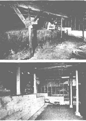
Figure 10.16 (A) A new beam, temporarily supported by braces atop
steel pipes. (B) The same beam, with new posts and the steel pipes embedded
in a concrete grade beam/retaining wall.
The technology. Kevin has found steel pilings to hold well in the adobe soil of Northern California. These 3-in. (I.D.) pipes of No. 80 steel are driven down and sleeved every 5 ft (rather like oil-drilling pipe) until they hit bedrock. Frequently, pipes and sleeves fuse under the pressure. After hitting rock, the steel is hammered another minute or so, until it’s clear that it won’t go any deeper. As the point of the piling is hammered against the rock, it sculpts a cup which minimizes drift later. At the end of the driving there is a surge of a few inches which indicates the point of the pipe collapsing. At that point you stop. Each piling can take a vertical load of 30,000 lb.
The pipe’s point keeps the interior of the pipe clear, so that you can pour in adhesive and insert rebar; Kevin favors epoxy filler and No. 3 rebar to tie his pilings to the concrete caps he adds later. Sometimes in soft soil it’s appropriate to drive in pipe without a point, later pumping in concrete under pressure so that it displaces the dirt and mushrooms out of the bottom in a footing of sorts.
The solution. To pick up the main girder and incorporate it in the back wall of the new bedroom to be created, Kevin decided to cast a grade beam/retaining wall. After excavating a trench and building forms for that beam, he temporarily shored up the posts supporting the girder, added concrete and rebar to that line of pilings, then poured the grade beam. After the beam cured, the posts would rest directly atop it.
Bolstering the perimeter foundation was similarly inventive. Because the weakest point was the northwest corner where springs converged, Ken decided to jack up that corner and reinforce its two contiguous walls by tying them into several steel pilings capped with concrete cubes 2 ft on a side. Thus each piling, driven to bedrock, sported a cluster of rebar as in Figure 10.15C, further tied to rebar epoxied into the perimeter foundation. At some points it was necessary to drill up into the underside of the foundation to add the necessary rebar. In those cases the excavation holes themselves served as forms for the concrete that followed.