Despite their size, moat large appliances are relatively simple machines. On average, they are only slightly more complex—and slightly more difficult to fix— than small appliances. If you consider the cost of a service call or the cost of replacing a large appliance, fixing one yourself is usually well worth the effort.
Replacing a large appliance rarely requires special tools. Only screwdrivers, nut drivers, or wrenches are usually needed for disassembly— although a socket wrench will speed the process and help loosen stubborn fasteners. A volt-ohm meter (VOM) is the only special item you may need; for simple tests, you can often use an inexpensive continuity tester instead.
Moot of the large appliances shown in this section are typical freestanding models. In most cases, the repair process shown here can be easily adapted to built-ins and other models.
- Basic tests and repairs (this page --below)
- Air conditioners
- Central air conditioners
- Central heating systems
- Central heating systems / thermostats
- Dehumidifiers
- Dishwashers
- Dryers
- Garbage disposers
- Humidifiers
- Microwave ovens
- Ranges / electric
- Ranges/gas
- Refrigerators / frost-free
- Refrigerators / cycle-defrost
- Refrigerator /Icemakers
- Trash compactors
- Washing machines
- Water heaters
- Water softeners
- Whirlpools and spas
+++++++++++
Basic tests and repairs
The tests and repairs on these two pages are common to many large appliances. Familiarize yourself with this section and with Appliance repair basics before tackling any large-appliance repair.
When fixing a large appliance, it’s often helpful to refer to the wiring diagram; it’s usually located inside the unit—glued to a back panel, folded and tucked under a chassis strut, or sealed inside the door panel. If you can’t find it, call the manufacturer and refer to your appliance model number. Wiring diagrams are fairly easy to read. Even if you can’t follow one fully, it can be useful for identifying wires by color and tracing them to break down a circuit into its simplest components. It also shows if a switch is normally open or normally closed, or whether a motor is single or multiple speed. It includes charts that help you test selector switches and timers (below), and may include the VOM reading to look for when testing a component.
Cosmetic repairs for a cabinet:
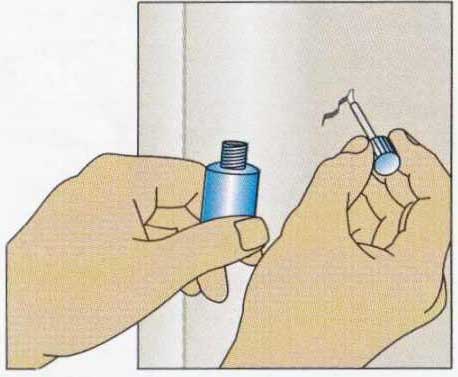
To fix a scratch, use appliance touch-up paint in a matching color (sold by appliance dealers and repair stores). Apply a tiny amount of paint with the bottle’s brush. Fill a deep nick in layers; let each dry before applying the next. Smooth with fine auto-finish rubbing compound.
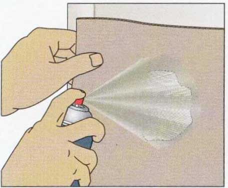
To spray-paint large area, use matching appliance spray paint. Cut an irregular hole in cardboard slightly larger than the damage. Hold spray can about 12 in. from surface with cardboard mid way between, and make several quick passes over hole to feather edges. Don’t let paint build up and drip.
Replacing a hose:
When removing a hose, wear safety goggles. Squeeze the spring clamp with locking pliers, slide it up the hose, then pull the hose off. Slit a stuck hose with a utility knife and peel it off. Replace a loose or corroded clamp with a worm-drive clamp.
Testing a timer motor:
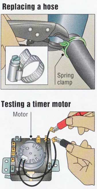
To test timer motor, track and free motor leads and probe them with VOM on RX10. Look for a relatively high reading (usually 2,000 to 3,000 ohms), indicating continuity. If reading is infinity, replace motor (if possible) or entire timer mechanism.
Testing a timer:

above: To test timer, check timer chart and note which contacts should close during part of cycle that isn’t working. Set timer knob to that part of cycle; then disconnect and label leads for terminals that should close. With VOM on RX1, probe each terminal pair. Look for a zero reading on each; replace timer if reading is infinity or high ohms.
A timer energizes inlet valves, motors, and other parts at the proper times. If a timer is dead, test its motor if the motor’s leads are accessible (right). If a timer malfunctions, check first for loose wires or burnt terminals. To check it more fully, use the chart on the wiring diagram that shows its terminals designated by letters, numbers, or wire colors. Some charts look complex, but they can be deciphered with a little study. The (partial) chart below is for a dryer.
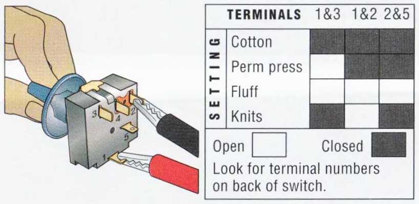
Testing a selector switch:
A multi-position push-button or rotary switch lets you select a fan speed, water or air temperature, cooking mode, or long or short cycle. Before testing a mal functioning switch, check for loose wires or burnt terminals. Try spraying the switch with electrical con tact cleaner. To test the switch, find the chart on the wiring diagram that shows the switch terminal designations (letters, numbers, or wire colors) and the switch positions for each switch setting.

above: To test selector switch, remove leads and label them. At each switch position, use a VOM set on RX1 to probe all terminal combi nations in the switch chart for the appliance. Look for a zero reading when the chart shows closed contacts and infinity otherwise. Replace a switch that deviates from results noted in chart.
= = =
!!! FOR YOUR SAFETY !!!
!!! Unplug any appliance before testing or fixing it. If t is wired directly, turn off the power to it at your home’s main service panel. Electric dryers and ranges have two “hot” wires; turn off the double circuit breaker or take out both fuses.
Test for a ground fault after servicing any electrical part of an appliance. With a VOM on RX100, probe bare metal on the exterior of the part and each terminal in turn. Look for an unvarying reading of infinity; if it’s not, make sure no wires have been accidentally grounded, or replace the part.
If an appliance has a capacitor for its motor, always discharge it before testing or servicing the motor.
= = =
Testing a thermal cutoff or disc thermostat:
A thermal cutoff is a safety thermostat that turns off iii appliance before it overheats. Like a thermal cut off, a disc thermostat opens or closes a circuit at a set temperature; it’s used to regulate the operation of appliances such as dishwashers and dryers. Both devices have an internal disc made of two metals that expand at different rates. At a set temperature (stamped on the units metal flange with an F after it.), the disc flexes, closing or opening the contacts.
Most of these nonadjustable thermostats turn off a circuit at a high temperature (to prevent overheating or to turn off a heating element when the water is hot enough); they are tested as shown below. A disc thermostat that turns on a circuit at a high tempera ture (to start the motor when the water is at the right temperature) is tested the same way, but should give opposite results: infinity at room temperature and zero when heated.
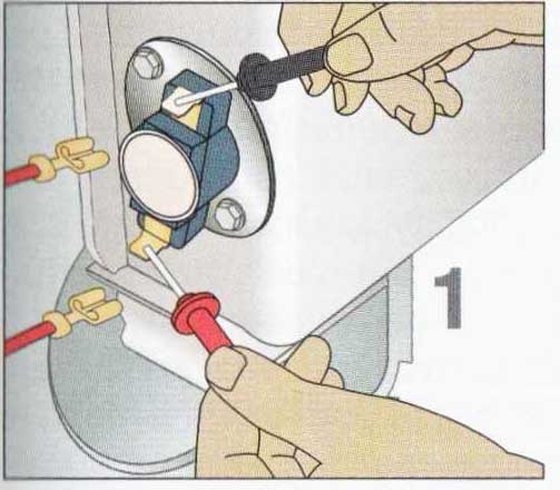
1. To test a thermal cut off that turns off a circuit at a high temperature, set VOM on RX1 and remove a lead. At room temperature, probe both terminals; look for a reading of zero. If cutoff tails this test, replace it. If it passes, go to Step 2.
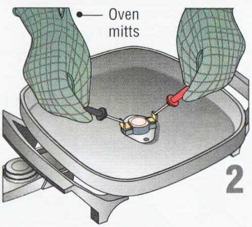
2. Remove the cutoff and put it in a electric skillet or a heated oven, or hold it next to a hot light. Heat the cutoff to a temperature higher than the one stamped on its metal flange. After you hear a click, probe again; look for a reading of infinity. Replace the cutoff if it tails this test.
Testing an adjustable thermostat:
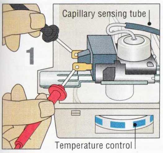
The temperature control on air conditioners, refrigerators, and ranges is usually an adjustable capillary thermostat. It has a long sensing tube filled with liquid (or gas) that expands when heated, closing electrical contacts. When you raise the setting, the distance between the contacts increases so that the liquid has to get hotter and expand more to close them. Lowering the setting does just the opposite. The test below is for an air conditioner or refrigerator thermostat. A range thermostat should read zero at room temperature when set on its highest setting. The best way to test it at a high temperature is to turn on the oven for 15 minutes and compare the thermo stat’s setting against an oven thermometer.
1. To test a thermo stattor a cooling appliance, set it on its coldest setting and test it at room temperature. With VOM on RX1, remove leads and probe both terminals. Look for a reading of zero. If the thermostat fails this test, replace it. If it passes the test, proceed to Step 2.
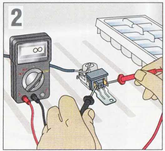
2. Remove the thermostat, set it on its hottest setting, and put it in a working freezer (or immerse it in an ice bath). After 15 mm., probe again; look for a reading of infinity. Replace thermostat if it fails this test.
Testing a motor:
Most large appliances are run by a split-phase motor. Before testing this usually reliable motor, check its starting components—the capacitor , if any, which provides an extra power surge to start the motor, and the centrifugal switch or the start relay , which disengages the motor’s start windings once it approaches full speed. Only a pro can test a motor fully, but you can test the motor’s windings for continuity. If a winding does test faulty, it’s usually more cost-effective to replace the motor.
CAUTION: Always discharge the capacitor before testing a motor.
To test motor, trace and disconnect leads. Set VOM on RX1. Clip one probe to common lead (usually white); probe other leads in turn. (There’s one lead for start winding and one for each motor speed.) Look for low to moderate ohms reading, indicating continuity with some resistance. A reading of infinity or near-zero ohms indicates a faulty winding.
Testing solenoids:
A solenoid is an electromagnetic coil with a central plunger that pulls in when the coil is energized and drops out when the current goes off. This allows it to perform such functions as opening water inlet valves, releasing detergent dispensers, and locking doors.
To test solenoid coil for continuity, remove a lead. With VOM on RX1, probe both terminals. Look for a reading of low to moderate (typically between 100 and 2,000) ohms. A high or infinity reading indicates a broken or melted coil. A reading of zero indicates a short circuit. If a coil is faulty, it can usually be replaced.
Next
Prev.
