Utility Trailer

4 x 8 Utility Trailer--Construction Instructions
This trailer is designed specifically as a heavy-duty, utility trailer with a low profile bed and options for versatility. The design incorporates strength in the main frame rather than requiring sides - even short sides - to give adequate strength. This trailer is designed tough for long, faithful service - though it may be a little heavier than some. This approach allows the trailer to be used in numerous ways for maximum utility and versatility.
Your success with the trailer is dependent on the care given in construction - including materials used, construction techniques and assembly methods. If you build it well, it will perform well. Load capacity is dependent on the axle, tires, options and proper load application. The specified capacity does not include capabilities of purchased parts like the hitch, chain, axle, tires, etc.. Do not exceed manufacturer limits.
As a reminder, these plans are for individual use only. Any use of these plans for resale or for producing products for sale is prohibited. Licensing for production and/or resale is available on request. Intellectual property rights for all materials are reserved. We thank you again for honoring these terms.
We truly hope you will enjoy your trailer, and to help ensure that, we have included a section of Towing Tips at the end. Please use caution and proper safety equipment while building and using the trailer.
Components Required:
- Axle Assembly:
Axle with spring centers at 48". Several variations are available. The axle you choose should fit your particular application and the vehicle you will be towing it with. The following items must be considered when choosing an axle:
• Axle Capacity - This trailer design will accommodate a load capacity of up to 3500 lbs. Typical available axles are 2000 lbs and 3500 lbs. Choose one applicable to your requirements. This will determine how much weight your trailer can carry.
• Straight or Drop axle - this will determine, in part, the bed height. A drop axle will lower the trailer 4" from the straight axle. If you are pulling it with a truck or other high clearance vehicle, the straight axle will probably match better. If you will be pulling with a car or minivan, the drop axle may be a better choice. Also consider loading the trailer - if ramps are used to roll things on and off, the drop axle and lower bed may be better.
• Underslung or Overslung Springs - this will also effect trailer height - over-slung is higher. We recommend underslung springs for better towing stability.
• Spring Type and Length - Typical trailer leaf springs are available in "Slipper" and "Eye" styles. We recommend the eye style because they make less noise and move some with a load. It can be argued that they help stability with a single axle arrangement. Springs come in various sizes or lengths (distance from eye to eye). We recommend longer springs for a softer ride. The 27" eye to eye spring length is shown. This trailer is not designed for coil or pneumatic springs.
• With or Without Brakes - this will effect your stopping distance. If you carry heavy loads, particularly with a lighter vehicle, we recommend using brakes. Next choose Hydraulic or Electric brakes. Electric is more common, and easier to adapt to other vehicles. Research this topic if you need more info. Some states don't allow surge hydraulic.
Axles can be purchased from Rigid Hitch, Northern, or many other places.
The axle shown in these instructions is Rigid Hitch # M-D3548-E - 3500#, 4" Drop axle, 27" springs centered and underslung at 48" with electric brakes. This comes with all mounting hardware required.
- Wheels and Tires - these must match the axle bolt pattern. Specific trailer wheels and tires are usually available with the axles, but another option is automotive parts. Most axles match an auto bolt pattern (like a Ford 5-bolt) so common rims and tires can be used. For a great look, nice wheels can be purchased from a scrap yard and standard tires can be mounted. Be sure the load rating of the tires matches the load you expect. Also, if wheels and tires for the trailer match those of the tow vehicle, an additional spare may not be necessary.
- Trailer Fenders - we recommend heavy-duty fenders like the Rigid Hitch #8433. Fenders come in different sizes, configurations and materials. Choose plastic or composite for harsh weather conditions. (Though you'll have to find a different way to mount them.) The fenders must accommodate the tire size and width. Check to see if your state requires fenders.
- Trailer Ball Coupler - must fit the ball size you use. We recommend a 2" ball and class IV receiver for a 3500 lb trailer. To mount on this trailer, the coupler must accept a 3" square tube. Rigid Hitch part # 22-300 is pictured in these instructions.
- Safety Chains - are required in most states for trailers over a certain size or weight. Generally, we recommend safety chains. Rigid Hitch part # 51 will be adequate.
- Lights, Wiring and Electric Connector - these items will depend on taste, choice of brakes, and connector type. For lights, the Rigid Hitch parts # 3504 (left) and #3554(right) are water- resistant and will nest in the rear channel of the trailer. Side marker lights (if needed, depending on state laws and your preference), wiring and connectors, must also be selected.
We suggest a liberal wire size and length. It can help avoid future problems.
- Optional Equipment:
• Tongue Jack and/or Swivel Wheel - to help in loading the trailer and moving it when not attached to the vehicle. Rigid Hitch # TJD-125 will fit most applications with this trailer. It will jack up the tongue, roll around, and snap up along side the tongue tube when the trailer is in tow.
• Hitch handle - to lift tongue up to the hitch - not of much use with a heavy trailer or load.
• Toolbox - pictured in some views. Many varieties exist from vendors like Rubbermaid, and can be found at stores like K-Mart or Wal-Mart.
• Trailer Sides - pictured in some views of this trailer - may be temporary or permanent.
Materials:
- Steel
• 4" x 5.4 lb. C-Channel
- 2 @ 96" - main rail channels.
- 1 @ 50.5" - rear bed bumper channel.
• 2 1/2" x 1 1/2" x 3/16" Angle
- 5 @ 50.14" - cross members.
• 2" x 1 1/2" x 3/16" Angle
- 1 @ 50.5" - trailer bed front.
- 2 @ 18" - rear angle braces.
- 1 @ 10" - bed support angles.
- 1 @ 50.5" - bent front angle.
- 2 @ 48" - axle spring mount angle.
• 3" x 3" x 3/16" Square Tube
- 1 @ 96" - tongue tube.
- Bed:
• 2 1/2" x 1/4" Flat Stock
- 1 @ 60" - tongue stiffener beam.
- 2 @ 12.5 - tongue stiffener gussets.
- 4 @ 11" - Fender mounting brackets.
• 4" x 1/8" Flat Stock
- 2 @ 42" - axle spring mount bolt plates.
- 2 @ 23.75" - front fascia.
• 6" x 3/16" Flat Stock
- 4 @ 6" x 6" x 45° - frame gussets.
- 1 @ 15" - tongue gusset.
• 1" x 1/4" Flat Stock or 1" x 3/16" Flat Stock
- 4 @ 7" - optional tail light protectors - not needed with optional hinged tailgate.
• 4 x 8 x 3/4" Plywood Decking - 1 sheet - consider grade and treatment.
- 1/2" - 20 x 1.25" Grade 8 Bolts with locknuts and washers - 6 - for securing axle assemblies.
- 3/8" - 18 x 1 1/2" Carriage Bolts with locknuts and washers - 20 - for securing plywood decking.
- 1/2" - 20 x 4" Grade 8 Bolts with locknuts and washers - 4 - for securing hitch coupler.
- Wheels, Tires and Lugnuts - many sizes and options available - 14" or 15" wheels - a variety of tire sizes will work. 215-70-R15 tires are shown. Be sure to match load requirements.
- Paint and/or other finishing supplies (depending on finish desired)
- Ramp Option:
• 3/4" x 3/4" x 1/8"
Angle - 2 @ 96" - under trailer ramp storage support angles.
• 2 1/2" x 1/4" Flat Stock
- 2 @ 90" - ramp side stiffener.
- 2 @ 5.25" - ramp catch plate ends.
• 4" x 1/8" Flat Stock
- 1 @ 23.75" - ramp catch plate.
• 2x4 or 2x6 x 8' boards - 3 - for wood ramp core.
• 4 x 8 x ½" Plywood - 1 sheet - for wood ramp core.
• 1/2" x 4" steel rod - 2 - for ramp catch plate.
• 48 #8 x 2" wood screws.
- Sides Option: will depend on your preferences, side height, top or no top, gate or door configuration, permanent or removable, etc.. See drawings for more information.
** Due to the vast number of different requirements for sides, the plans show several options, but materials required to build the sides are not included in this list. However, sides shown in drawings are made from 2" x 1" x 1/8" Rectangular Steel Tube and 2" x 1.5" x 3/16"
Angle for the framing. 1/2" plywood is used inside.
Tools Required:
- Saw, to cut steel (circular saw may be used with a metal cutting abrasive blade).
- Saw, to cut plywood and wood spacers (if applicable).
- Welder capable of welding steel at 1/4" thick.
- Hand grinder - for grinding welds and fitting metal pieces.
- Adequate Drill and drill bits for 1/4"- 5/8" for wood and steel. See drawings.
- C-clamps (many, varying sizes).
- Straight edge (min 48").
- Square and Tape measure.
- Wrenches, pliers, screwdrivers, Hammer, files and other common hand tools.
Component Suppliers:
- Rigid Hitch Inc. 3301 W Burnsville Pkwy.
Burnsville, MN 55337-4290 Phone: 800-624-7630 or (952) 895-5001
We like Rigid Hitch (even though they don't have a web site) because they carry higher quality components. They might be a little more expensive and they'll probably refer you to a dealer.
- Search the Internet. There are lots of places that sell trailer parts and accessories on line.
- Check Local Sources. Most cities and towns have a local source for trailer parts and accessories. Check local listings. This is a great way to see things prior to purchase.
1. Locate and Print the trailer drawing sheets.
- If you ordered complete printed plans, the drawing sheets are included in the package.
- If you received plans electronically, the same drawings are provided in PDF format: 4x8utrailer-drawings.pdf Print the drawings at the desired size (the Acrobat Reader gives options for print size or to shrink large pages). Contact a local Kinko's or similar print shop if you want a larger size and need assistance printing it. (Max size is C, 22"x17")
2. Look through these instructions and the drawings to determine which options you wish to include on your trailer, then get the appropriate components and materials.

3. Layout the trailer outer 4 members of the frame. Layout the 4 perimeter sections (2 c-channel sides, c-channel back and angle front) shown on Drawing Pages 3 & 4 for the main trailer frame. It may be easiest to lay this out upside down since the "top" is all at one level. Use clamps and straps to assure the parts will not move. It is often a good idea to clamp a few diagonals across the frame to hold position. It is also good to check that the measurement from opposite corners is equal-- this will validate squareness.
4. Tack weld the 4 corners then check squareness and flatness again. Make any adjustments necessary. It is critical at this point that squareness is established as a sloppy start will yield a sloppy finish, and this will effect how well the trailer tows.
5. Lay in the cross members. Use 1.25" thick boards or steel under the cross members (with the main trailer frame still upside down) as shown in the figure below. With the spacers, the cross members will all line-up vertically and will all lay flat to the bed. Make sure to notch the 2 cross members for the tongue as shown on Drawing Pages 3 & 4.

5x10 Trailer frame shown. 4x8 trailer frame similar (see drawings).
6. Tack weld the cross members in place. Keep checking squareness as you go because welds tend to "pull" as they cool and you need to keep the frame square.
7. Layout and tack in the angle braces and gussets shown on Drawing Pages 4 & 5. Again, keep checking squareness as you go.
8. Tack weld in the bed support angles shown on Drawing Page 5. Use the same spacers used with setting the cross members to assure a flat bed.
9. Lay in the tongue tube. The tongue tube is set in place in the notches cut in the front two cross members as shown on Drawing Pages 4 & 6. It must be square with the trailer frame for stable towing. This can then be tacked in place.
10. Lay in the bent front angle. This angle can be pre-bent if you have the equipment, but it can also be tacked in place over the tongue then bent down at each end (using large c-clamps) then tacked in place. When the final weld is done, the heat from the weld will stress relieve it. Some grinding on the front cross member may be necessary to get a good fit. On Drawing Page 6 a little interference can be seen in the front view. Carefully grinding the front cross member will make a great fit. Another view of this member is shown on Drawing Page 4.
11. Lay in the tongue stiffener and gussets. The tongue stiffener can also be bent and welded in place as done with the bent front angle. For a 2000# capacity trailer, this member is not necessary.
For the 3500# trailers, this will stiffen the tongue to better support a front loaded trailer.
12. Optional: Add the front fascia plates. Add the front fascia plates shown on Drawing Page 7 on either side of the tongue tube. These plates are primarily for aesthetics but will also stiffen the front and help keep "crud" from the tow vehicle out from under the trailer. These can extend the life of the trailer by protecting it from rust in the hard-to-paint corners.
13. Double check Squareness. At this point, all the structural members of the main trailer should be tacked in place. If it is square and flat to your liking you are ready to weld it all together. If there are tweaks to be made, do it now.
14. Completely weld the trailer frame together. Start in the corners, and stitch in a few areas. Do not complete any one full weld until you have added several tacks to all the joints - especially the angle braces and gussets. Check squareness again. Then complete the welding. By doing a little at a time as you go around, the likelihood of creating a "pull" out of square is greatly reduced. The extra effort will be well worth it.
15. Construct the Axle Spring Mounts. The left side axle spring mount is shown on Drawing Page 9.
You will need a right and a left. Care should be taken to make sure the holes line up as shown. The spring anchors shown on the drawing should come with the axle and spring hardware. We recommend that the spring mounts and springs be assembled together for tack welding on to the angle iron to assure proper alignment. Disassemble to complete the welds. Be sure to cut the bolt clearance area before welding the rear bracket on.
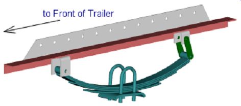
These spring mounts will be used to attach the axle to the trailer frame. The axle spring mounts can then be moved fore or aft on the frame to better balance the trailers load. In this way the trailer can be balanced to tow stable regardless of the load distribution (front to back) on the bed. If the movable axle option is not desired, the line of holes in the plate can be omitted, then the axle mounts can be welded to the trailer frame.
16. Build the Axle. Assemble the axle components including the axle spring mounts built in the previous step as shown in on the Drawing Page 9 and in the picture below. The tires and wheels must also be assembled. (Note: because the straight axles are typically slightly narrower, if you are using wide tires with a straight axle, you may need to get different rims (automotive rear drive) or shims to move the wheels away from the axle spring mounts.)

17. Assemble the fenders to the axle spring mounts. With the tires and wheels on the axle, measure for placement of the fenders. Clamp the fenders and mounting brackets to the axle spring mounts as shown on Drawing Page 9. Make sure to allow a few inches of suspension travel - 3" to 4" is adequate. We recommend you set-up and clamp both fenders and mounting brackets prior to welding so they can be set to match. Tack them in place then disassemble items (like tires) necessary to gain access for a full weld. (Note: if you think you will ever need to remove the fenders, you can bolt them instead. It won't be as strong or as sturdy, but it will make removal much easier. Also, if you are concerned about splashing from the tires to your load, you can fill the space between the fender and the axle spring mounts with sheetmetal or wood.)
18. Mount the axle assembly to the trailer frame. Hopefully you have a good way of managing heavy objects, because the axle and the trailer frame must now be assembled as shown on the Drawing Page 10. Measure carefully from the center of the tongue tube where the hitch will go diagonally to the center of the front spring bolts. This dimension must be the same for both sides. The dimension shown on the drawing is a recommended position that will be good for most applications; however, one of the great features of this trailer is the ability to move the axle as required for the load. When the axle assembly is in the right place, secure it to the frame with clamps.
19. Drill the first axle mounting holes. With the axle assembly secured in the proper position, drill through the 2 holes indicated on the Drawing Page 10 already in the axle spring mounts, through the c-channel web of the frame. These holes will be the base to measure from for the rest.
20. Drill the remaining axle mounting holes. After drilling the first holes, remove the axle assembly and re-drill the 2 holes slightly larger - depending on the accuracy used in drilling the first set and the holes in the axle spring mounts, you may wish to drill the holes at 9/16" (recommended) or 5/8". (This help the bolts go in later when the axle is moved.) Measure and drill the remaining 5 axle mounting holes in the c-channels of the trailer frame. This step is not necessary if you don't ever wish to change the axle position. Some disassembly may be required.
The movable axle option is beneficial for carrying widely varying loads, and for trailers that can adapt to specific load requirements. Adjust the axle position so that 12% - 20% of the load is carried by the tongue. Be sure not to exceed manufactures load ratings for the hitch, ball or receiver.
21. Position and mount the axle assembly. Reposition the axle assembly at the start location as shown on the Drawing Pages 10 & 11 (or other position if desired) then secure with bolts and locknuts. You should be able to use 3 bolts on each side in most every possible axle position. The possible axle positions are now in 3 inch increments forward and back. We strongly recommend using the plastic insert lock nuts on all fasteners of a critical nature. Vibrations from the road have loosened too many bolts to take a chance.
22. Attach the ball coupler. This is most easily done by clamping the coupler in place, then drilling through the holes in the coupler through the tongue tube wall. Once the holes are drilled, insert the mounting bolts and tighten. Again, use locknuts.
23. Optional: Mount the Tongue Jack and/or Swivel Wheel. If you have chosen to use a tongue jack or swivel wheel, mount it to the tongue tube. Most of these devises have bolts or plates that wrap around the tube. Make sure yours can fit a 3" tube. Drilling should not be required.
24. Wire the lights and brakes (if used). Check the laws of your state to determine requirements to be met for lighting and brakes. Get appropriate lights (running lights if necessary) then wire the lights, connectors and brakes (if used). Follow the manufacturer instructions. The picture below shows the mounting of the taillight from Rigid Hitch indicated above.

25. Wire the electrical connector at the hitch. Choose a connector for your options (electric brakes, etc.) and to match the tow vehicle. Purchase the connector and wire per manufacturer instructions.
We recommend protection on the wires to the connector like a sleeve to avoid damage with use.
Secure the sleeve and wires at the trailer tongue. An added welded bracket can be very useful.
26. Optional: Install the tail light protectors as shown on Drawing Page 12. The lights may need to be installed to assure proper placement, then removed for welding. Be sure to allow space between the protectors and the lights for installation and service.
27. Optional: Install Tie-down bars around edges of frame. Bars in front and behind the wheels can be added to the sides of the trailer frame for tie-down attachment as shown here.


These offer nice options for tie-down attachment - even with sides, these can come in handy.
28. Optional: Install Tie-down hooks or D-rings. For more versatility, tie-down hooks or D-rings can be installed in strategic locations - both on the bed and/or on the frame - for securing a load.
Many choices are available including recessed rings that can be mounted into the deck.
29. Assemble the trailer deck to the frame. Some trimming (or slight chamfering) may be required so it will assemble under the lips of the main frame c-channel on the sides. A deck top of 48" wide will slide first under one c-channel, then set on the cross members, then slide back to center (partially under both sides). The overlapping construction allows a low deck while allowing water etc. to escape from the surface. If you build a trailer with closed sides and top in extremely wet conditions, these areas may need sealant to keep moisture from the coming up from the bottom.
Drill through the cross members from underneath and through the wood with a 3/8" drill as needed for each cross member. 3 or 4 places evenly spaced. Use 3/8" carriage bolts to secure the decking to the cross members. Tighten the bolts until the head of the carriage bolt is just sinking into the wood. See the picture below.
30. Optional: Attach a tool or storage box. A tool or storage box can be added and mounted on the front section of the trailer if desired. The picture below shows a mounted box. Boxes for this use can be purchased at numerous variety stores like K-Mart, Wal-Mart, Target, etc.. Rubbermaid and others make weatherproof plastic boxes that will work. Most of these can be fastened by bolting through the bottom to the trailer. For better support, bolt a piece of plywood to the tongue triangle then bolt the box to the wood. To waterproof it, use a little sealant around each bolt.

----------- Trailer shown with optional toolbox and ramp.
31. Optional: Build the ramp. Construction details are shown on Drawing Page 13. This ramp is intended for people use, not heavy machinery. It is made of a wood core (2x4's and plywood), steel side stiffeners and a front catch plate. (2x6's can be substituted in the core for more strength (and more weight). 1/8" thick steel can be substituted on the sides for less weight (less strength).) This ramp is designed to be stored under the trailer on the 5' wide models. With the 4x8 trailer, the ramp can be used, but must be stored some other place. The catch plate hooks are designed to grab the back channel of the trailer frame for easy loading and unloading. The picture below highlights the ramp catch plate, the guide pins and the hooks. The holes in the plate allow easy attachment to the rest of the ramp. For greater strength, weld the catch plate to the side stiffeners.
Note: If this ramp is used with a flush top deck option, the decking (trailer floor) must leave a little space, between the back channel and the wood so the hooks can get around the channel. The hooks on the catch plate keep the ramp from sliding off the back of the trailer when it is being used.

32. Optional: Build trailer sides. If sides are desired, they can be added in a number of different ways. If you need sides, consider the height and strength required. Also consider if the sides need to be permanent or if they must be removable. If removable, consider the process for taking them on and off. Also consider weather proofing of the interior if that is desired.
In the plans several variations for sides are shown, however, because of varying needs for sides, only a few specifics are given and exact materials are not listed. If sides or a top are desired, use these instructions as recommendations, then plan and incorporate sides as desired. In particular, we recommend completing the main trailer then measuring and fitting sides per your needs.
To add sides, measure and build from the completed trailer frame. Take note of how the tailgate or back door will interface with the sides. Weld (or bolt) the uprights at the corners to give stability. We recommend welding if the sides aren't removable. Be aware of the axle and its positions when locating the uprights - they may limit axle movement. Sides shown in the drawings are made from 2" x 1" x 1/8" rectangular steel tubing and 2" x 1.5" x 3/16" angle, with plywood as an inside liner.
Optionally, the framing can be made from any materials desired. Strength and use must be considered when choosing materials. Triangulation my also be considered and used for rigidity.
Use the included drawings as reference to formulate a plan. There are several concepts presented to give ideas and some dimensions are shown only for reference. Since you are building your own trailer, you are obviously smarter than average in this area, so figuring out sides with the help of the included drawings will be fairly easy.
Depending on what you want, the frame may overlap the plywood or not. The plywood may want to be at the same height as the frame, or extend slightly above. If a top is desired, an angle iron piece can be used over the top edge of the plywood to make a secure mounting surface for sealing (see picture). Length of the uprights may be different depending on the way the top is handled.

For aerodynamic efficiency, add the half-pipes to the front (as shown in one drawing view). These can make a significant aerodynamic effect - especially since the trailer will be immediately behind the tow vehicle. Rounding just the edges can reduce wind noise and increase efficiency.
For access to the inside space, consider a gate or door and whether that should slide in, hinge to the right, hinge to the left, split in the center, bolt-on, etc.. When considering a gate or door, make sure the sides accommodate its attachment. Latches and hinges of many varieties are available to meet your needs. Shop around to choose the best approach for you.
If you use the included option for the hinged tailgate/ramp, the sides will need to accommodate a connection from the lifted gate to the sides to secure it for traveling. That can be as simple as a couple of holes to allow a pad lock to be latched through.
33. Optional: Attach a spare tire. There are two easy locations for the spare tire (if you wish to have one). The first is on the tongue - there are several bolt-on products available to accomplish this.
The second location is under the back of the trailer.
Another option for a spare is to have the trailer wheels and tires match those of the tow vehicle.
That way, if the tow vehicle carries a full size spare, it could be used for either the trailer of the tow vehicle should you need one.
34. Paint and finish the trailer to reflect your own personality. We strongly recommend taking the time and effort to protect your investment. Prepare the steel by sandblasting if possible, then use a good primer and paint. We recommend 2-part epoxy based primer available at most industrial paint centers. (Powder-coating the frame can be even better than paint, but requires special equipment. Usually, it is fairly economical to have done.) Use an industrial outdoor rated primer and paint on the wood parts - house paint will not usually last very long. Consider where the trailer will be used when making your choices about paints.
35. Hook it up and take it for a spin! Enjoy it, you've earned it!!
Options:
Several options are included with these plans. Things like motorcycle stands, various tie-down options, multiple sides ideas and ramp options. Consider your needs and incorporate the options that best fill those needs. You will likely have the trailer for a long time, so take a moment and think about what options will be best. You'll be glad you did.
Towing Tips:
- Secure all bolts and fasteners in vibration resistant ways - use things like Nyloc nuts, Loc-tite, cotter keys or wired nuts. Be sure the methods are appropriate for the situation.
- Check bolts, fasteners, lights and brakes prior to towing.
- Inspect the trailer regularly to assure there are no cracked welds, loose bolts, or other issues that can create problems.
- Inspect the spare tire (if used) to be sure it is inflated properly and in good condition.
- Double check the hitch to be sure it is connected securely.
- Use tow chains and secure them to a sturdy part of the hitch.
- For stability, distribute the load on the trailer evenly - not disproportionate on one side or the other.
- Again, for stability, the trailer load should be such that 10% - 20% of the load is on the tongue.
- If you have a problem with swaying or instability, re-distribute the load. Most instability issues come from improper trailer assembly (things not lined up or square) or from improper load distribution.
- Don't overload the trailer. Also, be aware of the towing limits of the pulling vehicle and the hitch.
- Don't overload the tires. Tires on trailers often have a lower capacity than the axle they are mounted on. This is a great way to have a blow-out.
- Secure the load so it won't shift or move in transit. Keeping a low center of gravity is also good.
- Double check tie-downs, tarps, ropes, etc. to be sure nothing will be "flapping in the breeze" or dragging the ground.
- Set tire pressure appropriate for the load. When is traveling empty, tire pressure may be reduced to 10 or 15 psi. This will allow the tires to absorb bumps and other anomalies, keep the trailer from bouncing around, and shaking the tow vehicle. Full tire inflation pressure is needed for a full load.
- If the trailer has high sides or a tall load, avoid traveling when high cross winds are present.
- Allow added distance for acceleration and braking. Even if the trailer has brakes, it can take more distance to stop.
- Allow more girth around corners - take the corners wide - to avoid hitting the trailer tires on a curb, because the trailer takes a shorter radius than the tow vehicle. Also, the longer the trailer, the more space it takes.