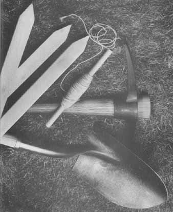
The basic tools. A pick and shovel for moving earth, and stakes and string for making guide lines, are the tools to start most outdoor construction.
Simple hand tools like these serve for all but the most extensive earth-moving
projects, but unless you are accustomed to swinging a heavy pick, schedule
your digging work by installments to avoid hand blisters and backaches.
Whatever the shape, size or conformation of the land around your house, you can probably improve both its looks and its utility by adding a few easy-to-build yet sturdy and handsome outdoor structures. Toolsheds and garages protect belongings; shade houses, gazebos and garden ponds add comfort and charm. Fences and walls not only ensure privacy and define boundaries but, with artful geometry, provide attractive backdrops and , through skillful placement, moderate the force of the wind and the flow of frost.
The land itself can be remolded to create more pleasing contours, to improve drainage, to halt erosion or to prepare the way for the foundation of an outdoor structure. Most such construction starts with either leveling or excavating—or both—and may even involve a little surveying, a fascinating and easily mastered technique. Earth- moving requires a fairly intimate knowledge of both the surface and the subsurface of the property. Before you start building, find out whether local building and zoning codes dictate drainage patterns, fence heights or road easements. In any case, property lines, septic tanks and underground power, water and gas lines always must be marked out before any excavation work begins. In many regions of the country, utility companies will stake out the locations of their lines and pipes on request and free of charge, while county engineers will conduct soil tests to ensure that the ground is strong and stable enough to support a planned structure.
The techniques and materials described in this guide are not as complex or as costly as those used on a home. The exterior concrete slabs shown here, for example, are reinforced with steel mesh, but in most cases they are thinner than one poured for a house, and many light structures can rest on precast piers or, like greenhouses and fence posts, may be set directly in or on top of the soil.
The structures themselves are similarly simple to construct. Many are open, designed to direct and encourage a pleasing flow of light and air. For such buildings, an unusual variety of construction techniques is available: post-and-beam7for example, allows the builder to use 4- to 8-inch-thick members that can bear tremendous loads and are spaced at greater intervals and with somewhat less precision than is found in residential framing. A-framing, where walls and roofs are identical, is also convenient, while domes, built like bubbles without interior bracing, are ideal for areas where posts, beams and studs would be impossible or undesirable to use. When you are building relatively small, open structures, these methods eliminate the need for costly framing materials and for the advanced carpentry skills and precision workmanship required for homebuilding. They make buildings that any amateur can put up—and be proud of.
Surveying Property with Speed and Precision
The property lines that define the boundaries of a plot of land are seldom visible, but a landowner has to know where his property begins and ends when he plans an outdoor structure that could trespass on neighboring land. To find his boundaries, the landowner must use the findings of the professional surveyors who originally established and staked out the dimensions of his property.
The dimensions determined by the surveyors are marked on the lot plat, or map, that's generally furnished with the title to the land and is kept on file at a local courthouse or record office. When map ping the land, the surveyors also drive stakes, usually made of metal, into the ground at the corners of the plot to serve as property markers. These stakes may be lost in undergrowth or buried beneath a few inches of earth. But if they are metal, and as long as you can locate one of them, your property map and a little basic geometry will enable you to find the others. And with all the markers located, you can determine the boundaries by driving stakes next to the markers, then stretching string between the stakes.
Once the boundaries are established, a few simple surveying techniques and tools will enable you to map the location and size of the structure you want to build. Distances can be measured fairly accurately with string, wooden stakes, a carpenter’s tape measure and a roll of light-gauge tie wire, available at hard ware stores. A professional water level or a water-filled length of transparent gar den hose makes a precise tool for deter mining heights or slopes and establishing level points; when exact measurements are not essential, an inexpensive line level will serve the same purpose.
Some jobs, however, call for a degree of accuracy that can be attained only with specialized surveying instruments.
To measure exact vertical and horizontal angles, to sight lines for pouring foundations, or to establish perfect parallels to property lines, you should use a transit level, a telescope-like device with which builders, engineers and surveyors per form a variety of measuring tasks quickly and very precisely. Transit levels can be rented from surveying firms and , like any precision tool, they must be handled carefully. Do not, for example, use one on an excessively damp day: moisture can affect the accuracy of the readings on the instrument.
Caution: any measurement no matter how carefully taken, is only an approximation and even official surveys may not be totally accurate. To avoid the possibility of accidentally infringing upon a neighbor’s land, always stay at least 12 inches within the boundaries of your property when you are planning the location of any outdoor structure.
Finding Property Markers
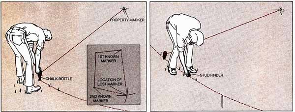
Using two adjacent markers. Drive a wooden stake next to an
established marker, attach a length of tie wire equal to the distance between
the established and the lost marker (as indicated on your property map) and swing the other end of the wire in an arc, using powdered chalk to
trace the arc on the ground. Drive a stake at a second known marker and repeat the procedure, using a length of wire equal to the distance between
the second marker and the missing one. Where the two chalked arcs cross
(inset), locate the lost marker by digging.
From a single reference marker. Using your property map and a tie wire to establish a point at the correct distance and direction from the marker, swing the end of the wire to run a chalk arc on the ground and walk a stud finder along the arc. When the stud finder’s magnetic needle deflects, dig for the marker. If the stud finder fails to deflect, then metal markers may be sunk too deeply, or else the markers are made of wood. In that case you will need to locate at least two visible markers or call a professional surveyor to reestablish the property lines.
Simple Sighting and Leveling Techniques
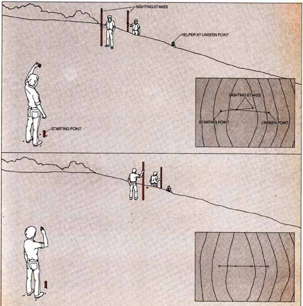
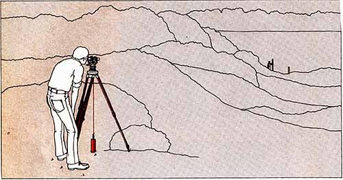
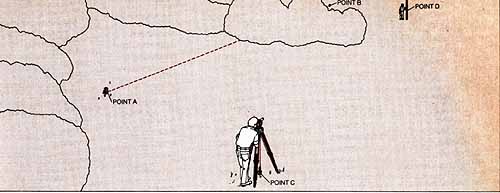
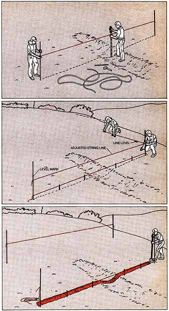
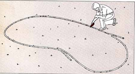
Sighting a straight line. To establish a straight line to an
unseen location—in this example, a point on the other side of a hill—drive
stakes at both the starting and the unseen point. Stand at one stake, station
a helper at the other and have two more helpers hold tall poles in between,
at points where the tops of the poles can be seen from both stake positions
(above, top). Sighting from your stake, signal the pole- men to move until
their poles are in a straight line of sight from your position. Have the
polemen turn around (bottom), let the other sighter move them until their
poles form a straight line from his position, then alternate sightings
until the poles appear in line from both positions (insets). Connect all
four points with a string.
Finding levels over uneven surfaces. Use a water level or
a transparent plastic hose partly filled with water to find on one stake
or post a point that's exactly level with a mark on another. Stretch the
hose between the stakes, hold one end a few inches above the mark you have
made and have a helper hold the other end at about the same height. Using
a funnel, fill the hose with water until the level reaches the mark. Make
sure there are no air bubbles—if there are, pour off the water and refill
the hose—then mark the second stake at the water level in the hose.
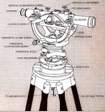
A Telescope that Measures Angles
Anatomy of a transit level. This professional surveying tool is essentially a tripod-mounted movable telescope with precise scales for vertical and horizontal angles. The 20-power telescope pivots at its center for vertical measurements and the entire mounting carriage rotates on the undercarriage for horizontal ones. To enable you to check the instrument for level and plumb, a small spirit level is mounted under the telescope and a hook for a plumb bob hangs from the base plate; the undercarriage slides over the base plate to position the bob, and four leveling screws are used to set the level.
Angles are measured on horizontal and vertical scales; when only horizontal measurements are needed, a pair of levers locks the telescope in the level position. Cross hairs in the telescope are focused by turning the eyepiece, and should only have to be set once; the focusing wheel provides a fine adjustment. For precise aiming, use the slow-motion screws to turn the telescope, and lock it in position with corresponding clamp screws.
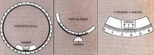
Measuring angles to the nearest degree. Vertical angles are
read on a 90-degree arc, horizontal angles on a circular scale divided
into four 90° arcs; small auxiliary scales called verniers serve as pointers
for the main scales and give readings in sixtieths of a degree, or minutes.
To measure a horizontal angle between two points to the nearest degree, focus the telescope on the first point and note the reading on the main scale closest to the zero mark on the vernier.
Swing the telescope to the second point and note the new reading. If both readings fall within the same 900 arc, subtract the first reading from the second. If the readings fall on adjoining arcs, follow these rules: when the arcs are separated by a zero, add the readings; when the arcs are separated by the figure 90°, add the readings and subtract the total from 180°.
Vertical angles up to 40° are measured above and below level, indicated by a zero.
Measuring fractions of an angle. If the zero mark on the vernier falls between two degree marks on the main scale, read ‘the lower mark and use the vernier to calculate the fraction in minutes. Reading upward from the degree mark, find the mark on the vernier that coincides with a main-scale mark. Count the vernier spaces between the two main-scale marks. Each space stands for five minutes; multiply the number of spaces by five to get a reading in minutes. The sighting below reads 17° 15’.
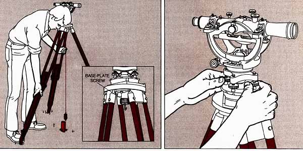
Setting Up the Transit Level
Plumbing the tripod. Spread the tripod legs 3 feet apart dyer a stake or other marker used as a sighting point and move the legs one at a time until the plumb bob hangs no more than ¼ inch horizontally from the center of the stake. Loosen the screw under the base plate and shift the transit level on the base plate until the plumb bob hangs directly over the center of the stake. Tighten the base-plate screw.
Leveling the transit. Loosen two adjacent leveling screws and turn the telescope until it aligns with two opposite leveling screws, then turn these opposite screws slowly until the bubble in the level is centered. Rotate the telescope 90° to align it with the other pair of opposite screws and repeat the procedure. Adjust opposite screws until the bubble in the level remains centered as the telescope swings full circle.
Getting Lines and Angles Exactly Right
Setting a straight line. Drive stakes at the two points to be aligned. Set up the transit over the starting stake with its locking levers open, focus on the other stake by using the cross hairs and tighten the horizontal clamp screw. Have a helper hold a stake at the approximate position of the next-to-last stake, lower the telescope and have the helper move his stake until you can focus on It; have him drive down the stake. Repeat the procedure for the other stakes.
12b Setting a right angle. Set a straight line to a stake, then rotate the transit level exactly 90 deg. on the horizontal scale and use the horizontal clamp screw to lock it in position. Have a helper move another stake until you can sight it in the cross hairs, then have him drive this stake in place. Check the angle by swinging the transit level back 90 deg. to the original stake.
How to Sight around an Obstruction
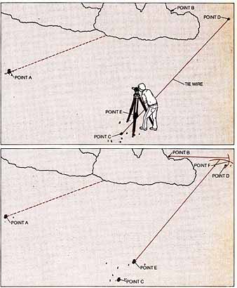
1. Plotting an approximate parallel. You will sometimes have to set a straight line parallel to a line that's obstructed, such as a property line running between points A and B in the example above. Set up the transit over a starting stake where the view is unobstructed—point C in this example—and sight a line approximately parallel to line A-B. On this line, drive a stake at point D so that lines A-B and C-D are equal. Stretch tie wire between points C and D.
2. Locating the first stake. From point C, rotate the transit 90° toward point A, and move the instrument along the line of tie wire until the cross hairs align with the stake at point A. Double- check the sighting by rotating the transit 90° toward point D; the cross hairs should align with the stake at D. Drive a stake directly underneath the transit (at point E), measure the distance between points A and E, and cut a length of tie wire equal to that distance.
3. Locating the second stake. Attach the length of tie wire to the stake at point B and swing it in an arc toward point D. Loosen the tie wire joining points C and D, fasten one end to the stake at point E and swing the other end in an arc toward point D. Plant a stake where the two arcs intersect (point F). The line joining points E and F is now parallel to the property line between points A and B.
Land Reshaped to Suit Your Needs
Flattening a stretch of land, creating subtle drainage gradients, controlling the runoff of surface water—these necessary grading jobs may sound vague and ambitious. They become exact and easy when you use the professional earth-molding techniques shown below. Moreover, you can do most of the work with plain hand tools.
Grades, which are areas smoothed and sloped for drainage, are made in two types. In one type a pair of fixed points, such as the street and the garage en trance at the opposite ends of a drive way, determine the slope. In the other, the surface of the ground is sloped just enough to drain off excess rain water, as may be necessary in a formal lawn, a patio or a setting for a garden house.
To set a grade having two fixed points, you must begin by measuring the difference in elevation—that is, the rise—between the points. The preferred ratio of the rise to the horizontal distance between the points varies, from 1 foot for every 10 feet of an entrance walk to 1 foot for every 7 feet of a driveway, and a maximum of 1 foot for every 3 feet of a grassy bank. If you find that the grade is too steep, you must build a solution into the site—adding steps to a walk, for ex ample, or building a retaining wall for a lawn. For a grade as nearly level as possible, the standard minimum is 1 inch of rise for each 4 feet of horizontal run (in porous soil where drainage is less of a problem, ½ inch is enough).
You can make these minimal grades by the string-grid method shown. The grid can also establish an ex act plane for a slope between fixed points—for example, a driveway. But you can dispense with the grid in grading a lawn between such fixed points as a foundation and a sidewalk, if the land has a slope of 6 inches or more in each 4 feet of run. In this situation your eye and your judgment will serve to make the grade sufficiently flat.
Grades are the major factor in the drainage of your property, and establishing grades that drain well must take priority over the cosmetics of landscaping. But professional land-shapers use other ways to drain land—by slowing fast run off, by diverting water from areas that are especially vulnerable to water damage and by draining water from any area in which it tends to collect.
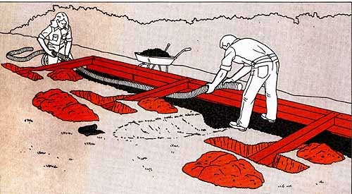
Use a double-ended pick with a point and a mattock to loosen earth for grading and draining. A plain pointed shovel with a long handle serves best for the digging. If you buy or rent a wheelbarrow for the job, get one with pneumatic tires and an oak frame. Rotary tillers with rear tines, available at tool-rental agencies, are comparatively expensive, but they till better and can be guided more easily than front-tine machines.
The fastest and easiest way to compact land is to roll it in two directions with a roller. But a roller is not sufficient if you have to fill; you must tamp the earth with a hand tamper or a power-driven ma chine tamper after putting down each 4- to 6-inch layer of soil or gravel. You must also tamp down the bottoms of swales, the slopes and tops of terraces and any area of soil that will lie under a concrete slab or a layer of gravel.
Making a Smooth and Sloping Grade
14 1. Establishing a rough grade. With a pick and shovel, cut down all mounds and ridges, moving the dirt into holes and valleys. If the slope runs in a direction different from the planned grade, use a wheelbarrow to move dirt from the high side to the planned new high side. As you work, either bury debris such as weeds, wood scraps and stones in a hole or pile it up to be carted away later. When you have finished, the grade should look approximately flat.
2. Tilling the soil. Use a rotary tiller to break up clods and make the soil easy to rake. Set the ma chine for deep tilling and till back and forth across the width and the length of the plot, making tight turns by releasing the drive clutch and swinging the tiller around on its wheels (or, for a front-tine tiller, on its tines).
3. Setting the slope of the grade. Drive stakes at the corners of the area to be graded. At one of the upper stakes tie a string 6 inches above the planned high edge of the grade, stretch the string to the lower stake on the same side and level it with a line level; mark the lower stake at the string. For a minimal grade, as in this example, measure 1 inch down from the mark for each 4 feet of string, and tie the string at that point. Tie level strings, from the first string to the stakes on the other side of the area, and complete the boundary with a fourth string. For a grade with two fixed points, dispense with the line level: tie the first string to the upper and lower stakes 6 inches above the fixed points, then complete the boundary.
To measure the rise of a grade for planning purposes, tie the string at ground level on a stake at the area’s upper edge and measure directly from the string to the ground at the lower edge.
4. Making a grid. Drive stakes at 6-foot intervals along the boundary strings and connect each opposite pair of stakes with string to make a grid. If any grid string touches the ground, scoop out the earth beneath it to form a trench.
5. Establishing the finish grade. Working under and between the strings, use a shovel and a rake to move the soil into a flat surface parallel to the plane of the grid; judge by eye to see that the middle of each 6-foot square is level with the sides under the strings. Add or remove soil as needed to bring the grade exactly to the planned height, then turn the rake tines up and use the back of the tool to finish-smooth the surface. Remove the strings and stakes and compact the soil by either rolling or tamping, depending on the function of the graded area.
Halting Erosion and Improving Drainage
Generally, the problems of surface drain age on a house lot have three causes: erosion, grades that direct runoff in an undesirable direction, and boggy low spots that accumulate water. Grading can solve problems, but the topography or the amount of earth to be moved may make this solution impractical. However, in most cases there are solutions that do not call for extensive grading.
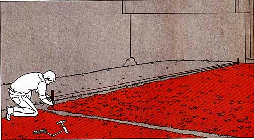
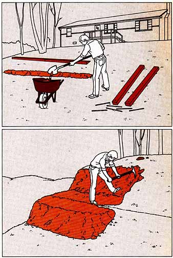
The easiest way to stop erosion is to slow the velocity of the runoff. One technique for doing so is to install baffles, such as the buried railroad ties shown at right. Baffles block descending surface water before it gains much speed; the water flows over a baffle and renews its run, only to hit another baffle. The baffles are set in the ground on a slight gradient, end to end, so that they will not hold water after a rain stops. And if the baffles are obtrusive and unsightly, they can be concealed with plantings.
Another technique for slowing the velocity of runoff water is to build a terrace without a retaining wall. Here, the water descending a short steep slope is stopped by the terrace before it can run fast enough to erode the soil. Terraces look better than baffles, but they take more labor to construct.
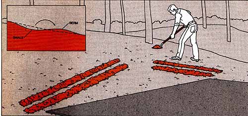
To stop runoff toward some vulnerable feature of a property, such as a patio, a mound for decorative planting, or a house foundation (where accumulations of water can cause basement flooding), the specific solution is an interceptor ditch called a swale. Located and shaped so as to be nearly invisible, the swale carries surface water sideways and diverts it around the object or away from the area to be protected.
The problem of standing water in depressions can be cured in two ways. One is the straightforward method of filling the hole. The other consists of draining the water into a dry well; it seeps away through the sides and bottom of the well. Where possible, connect the dry well by installing a drainpipe to a lower part of the land or to a storm sewer located on your property.
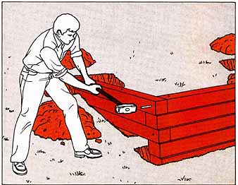
Slowing runoff with baffles. Across the face of a slope, dig trenches in an open zigzag pattern, making each trench deep enough to bury all but 2 inches of railroad ties or 6-by-6 timbers. Use a line level to give the trenches an end-to-end gradient of 1 inch for each 4 feet of length and start the high end of every course about 6 inches beyond the bottom of the course above, to make it catch end spillage from the course above. Pin the timbers to the ground. Caution: wear gloves when handling creosoted railroad ties.
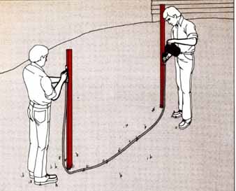
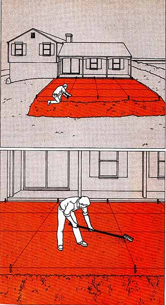
Slowing runoff with a terrace. Drive stakes about 18 inches vertically above the foot of the slope at one end of the planned terrace, stretch a level string across the slope and mark the ground along the string with chalk from a squeeze bottle; then dig into the slope above the mark and deposit the soil below it. Keep the drop-off of the filled part at the angle at which the soil falls naturally and shape the drop-off in the cut part to the same angle. Form the flat part of the terrace so that a basketball placed in it will roll slowly to the drop-off.
Channeling water with a swale. Above and to the sides of the object or area to be protected from runoff, dig trenches as wide as a shovel, with sides that slant upward at a low angle and meet in the middle. Adjust the depth of the trenches to the steepness of the natural slope — from 2 inches deep for a slope of 1 foot of rise to 6 feet of run, to 5 inches deep for a slope of 1 to 2. Throw the soil you remove about 18 inches downhill to form a low dam, called a berm; shave the upper shoulder of the trench back about 18 inches, adding this soil to the berm; then shave the lower shoulder back to the berm. Tamp the swale and test its internal slope by rolling a basketball down it.
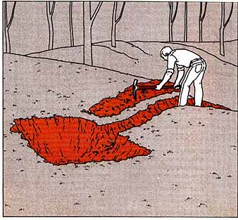
Excavating a Dry Well
1. Digging a hole. After deciding on the size of the dry well, dig the hole for it in the lowest part of the depression. Starting from the hole, dig a trench 18 inches below the surface, dropping at a slope of 1 inch in 4 feet to a lower part of your property. Install 4-inch perforated plastic drain tile in the trench, covering the ends of the tile with fiberglass cloth to prevent them from filling with dirt. Then refill the trench.
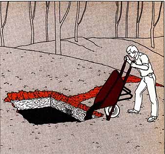
2. Installing gravel for drainage. Line the hole with 1-inch fiberglass insulation, fastened to the sides of the hole with sixpenny galvanized nails, and fill the hole with gravel to a level 8 inches below the surface. Cover the gravel with fiberglass and the fiberglass with soil.
Relocating a Recalcitrant Rock
Not often, but too often, a homeowner moving soil on his property hears his pick strike solid rock. Exploring further, he discovers that the soil conceals a large boulder exactly where the putting green or the garage foundation was to go. He may be happy to know that his property contains some big stones suit able for a rock garden—but the stone must be moved.
Any rounded stone bigger than 30 inches in its longest dimension weighs upwards of 300 pounds. In most cases a professional should move it, using a backhoe or a front-end loader. Even in dealing with smaller stones, you have to consider the dangers of back strain and loss of control. One simple way to get a large protruding rock out of your way— in relatively rock-free soil—is to dig a deep hole alongside it, and lever the rock down into the excavation. But if you feel confident of your muscles and prudence, you can move a stone measuring 30 inches or less with prybars and a makeshift wooden dolly. First, remove the soil around a deeply buried stone and dig a ramp to the surface. Then lever the stone onto a piece of heavy burlap, wrap the burlap around it and form the edges of the burlap into hand- holds. With a helper or two, skid the stone out of the hole.
Make the dolly from a 4-foot square piece of ¾-inch plywood laid on top of four lengths of 4-inch plastic drainpipe set about 14 inches apart. With a plank ramp, skid the stone to the middle of the plywood. Using the pipes as rollers, push the stone along the ground until the rear pipe is free of the trailing edge. Place this pipe ahead of the dolly and push again, repeating the process until the stone is just short of its destination, then tilt the plywood to slide the stone to the ground.
How to Terrace Slopes with Retaining Walls
For centuries farmers have turned steep hillsides into cultivable land. The technique is simple—they build an ascending series of retaining walls up a slope and fill the areas behind the walls with fertile soil until the ground is level. The same technique will serve to turn a sloping yard into a series of patios or gardens. Though most retaining walls are now built of timber, which is easier to work with and maintain than the traditional fieldstone of the farmer’s wall, the principles of construction remain the same.
Because earth and water create tremendous pressures behind a retaining wall, you must make your wall strong and provide for adequate drainage. Begin your planning by checking local regulations on drainage (any change in the con tour of your land affects the flow of water across it). In many localities a building inspector will examine your initial layout and make recommendations for drainage routes. For a wall more than 3 feet high, you will probably need a building permit, and may have to submit plans drawn up by a structural engineer.
The next stage of planning deals with the materials you will use. For the walls themselves, you can choose between railroad ties and pressure-treated lumber. The ties are inexpensive but they are soaked with creosote, which will quickly dull the blade of a chain saw and is poisonous to many plants. Redwood, which is handsome and naturally resists moisture, is perhaps the most popular wood for outdoor structures but is expensive. As a compromise, consider poplar or pine timbers, pressure treated with harmless preservatives, as durable as and much cheaper. They come in 6-by-6 or 6- by-8 sizes; choose B-foot lengths, the easiest to work with.
At the same time, decide upon the grade of lumber to order. Finish grade, the most expensive, comes with edges neatly planed and ends perfectly square so that you need not square the ends of every timber before butting it to its neighbor; less expensive grades make more work but save money. Whatever grade you choose, buy 20 per cent more timber than your calculations Indicate as a minimum amount, to allow for waste. An 8-foot timber weighs from 100 to 200 pounds; save yourself labor by planning access routes so that the lumberyard can stack your wood close to your job site.
At the same time, lay out routes for a gravel company’s delivery of drainage gravel and backfill, to be delivered some time after you have completed the construction of the wall. The gravel company will advise you on the best fill for your purposes; if you are planning gardens or lawns, buy shredded topsoil and mulch for the top 6 inches of fill. To determine how much fill you will need, calculate the volume of fill in cubic yards—the length of a wall (in feet) times its height times the distance from its base to the next wall. Divide the answer in half (be cause approximately half the space be hind the wall is already filled with existing soil), then divide the result by 27, to convert cubic feet to cubic yards. Finally, add 20 per cent to allow for compaction. For a drainage bed, order a ton of clean 1-inch gravel for each 25 feet of wall.
Beyond common household tools, you will need a chain saw and a heavy-duty drill fitted with a 3/8” electrician’s ship-auger bit 18 inches long. Anchor the wall to the hillside with three 42-inch lengths of 3/8” reinforcing steel—commonly called rebar—for every 8 feet of wall, and peg the layers of timbers together with three 12-inch pieces of 3 rebar for every 8 feet of wall.
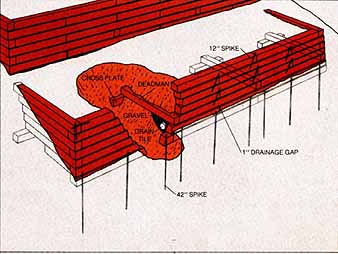
Anatomy of a retaining wall. Two timber retaining walls, each 3 feet high, terrace this hill side. Each wall consists of seven courses of 6-by-6-inch lumber. The first course, buried in a trench 6 inches deep, is anchored to the hill side by 42-inch spikes made of 3/8-inch reinforcing steel. Succeeding courses are pinned together with 12-inch vertical spikes, and overlapping timbers are spiked horizontally and vertically.
To help the wall withstand the pressure of the compacted earth behind it, each course is set ¼ inch closer to the hillside than the one below, and angled into the hill. Eight-foot reinforcing timbers called deadmen run back from the wall at 6-foot intervals, and the free end of each dead- man is attached to a crossplate spiked to the earth. As a final brace, side walls are built up on the outermost deadmen and connected to the retaining wall by interlocked corners.
To prevent water from building up behind the wall, the timbers in the second course are separated by 1-inch drainage gaps. In addition, 4-inch perforated drain tile buried in gravel routes water beyond the ends of the wall.
Preparing the Site
1. Marking the wall trench. Drive 5-foot stakes at the points you have chosen for the corners and tie a line between the stakes, using a water level to make sure it's horizontal; then measure down from the line to find the point where the line is highest above ground—the “lowest grade point.” Mark this point with a stake.
Adjust the line between the corner stakes so that it's 3 feet above the ground at the lowest grade point. Drop a plumb line every 4 feet along this line and drive stakes at these points to mark the outer edge of the wall. String a second line along the lower stakes.
2. Laying out a terrace. From the 3-foot mark on a corner stake, stretch a line into the hillside and level it with a line level, then drive a 5-foot stake where the line meets the ground. Measure the distance between the two stakes along the ground and drive a 5-foot stake at this distance from the other corner stake.
Use the two uphill stakes to establish the height of a second retaining wall.
3. Digging the trench. Starting at the lowest grade point, dig a trench 1 foot wide along the line that marks the outer edge of the wall. Mea sure frequently from the line that marks the top of the wall down to the trench bottom to be sure that the trench is level; for a wall 3 feet high, the trench bottom must always be 42 inches be low the string line. Remove the stakes.
With a chain saw, cut timbers to fit in the trench, making no timber less than 6 feet long.
Lay out deadman trenches at the wall corners and every 6 feet along its length. For each trench, place the shorter blade of a carpenter’s square parallel with an upper edge of the timber, stretch an 8-foot line back from the timber and up the hill parallel to the other blade, and drive a stake into the hill at the end of the line.
Building the Wall
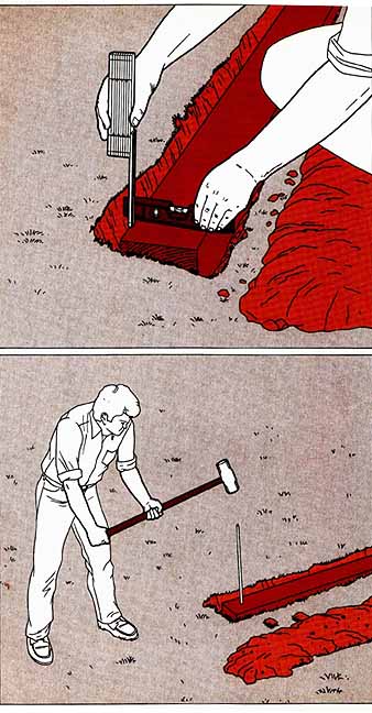
1. Setting the tilt. Level the first course of timbers in the trench and tilt each timber ¼ inch to ward the hill, propping it with small stones. Check the tilt with a ruler and a torpedo level held horizontally across each section; the gap between the bottom of the level and the top of the timber should measure ¼ inch.
At the center of each timber and 6 to 12 inches from each end, drill vertical ¾-inch holes completely through the timber, using a heavy- duty drill fitted with an electrician’s ship-auger bit.
2. Securing the first two courses. Using a 10-pound sledgehammer, drive ¾-inch steel spikes 42-inches long through the drilled holes in the timbers and into the ground. Check the level of the course and adjust the tilt if necessary. Then lay a second course of timbers upon the first, ¼ inch closer to the hillside. Leave 1-inch gaps between the sections of this course, and stagger the timbers so that the gaps do not align with the joints of the first course. Drill 3/8- inch holes through the timbers and drive ¾-inch spikes 1 foot long through the holes to pin the layers together.
From the top of the second course dig trenches 6 inches deep, 8 inches wide, and 8 feet long along the routes you have marked for the deadmen; the deadmen themselves will rest upon the second course of timbers. For the cross plates, dig trenches 1 foot deep and 3 feet long across the ends of the deadman trenches.
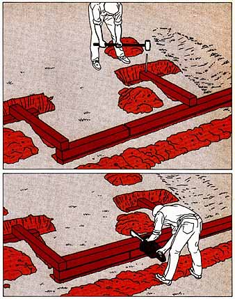
3. Bracing the wall. Cut and lay the deadmen and crossplates. Drive 42-inch steel spikes down through the deadmen and crossplates and into the ground, and drive 12-inch spikes through the deadmen and into the second course.
To start the third course of the wall, cut squared timbers to fit between the ends of the deadmen. Set the first timber next to a corner deadman and spike it in place.
4. Cutting tight joints. Set a second timber next to the first, butting the ends together, and make a cut across the butted ends with a chain saw; clean away the wood chips and push the timbers together. Drill a hole diagonally through the top of one timber, across the joint, down through the adjacent timber and into the second course of timbers below; drive a 12-inch spike through this hole to pin all three timbers together. Repeat this procedure until you have completed the third course.
Do’s and Don’ts for Chain Saws
A gas-powered chain saw has a chain of sharp teeth that rotate around a 16- to 20-inch guide bar. An automatic or manual oiler lubricates both chain and guide bar to keep them from overheating during operation. A well-made saw can cut heavy timbers in seconds.
Chain saws must be carefully maintained and operated. When you rent one, be sure that the teeth are sharp and the chain is tight—you should never be able to pull the chain more than 1/8” away from the bar. Check that the saw has a safety bar and that you have enough fuel and lubricating oil for your job. Have the dealer demonstrate starting and stopping procedures and watch him cut some scrap wood. When you use the saw, follow these rules:
- Before cutting a timber, remove all debris from the work area, remove any nails from the wood, and make sure that the timber is well supported. With a combination square, mark guidelines on the timbers you plan to cut.
- Use two hands to raise the saw.
- Make sure no one is near you when you work. Caution: a chain saw makes a deafening noise (you may want to shield your ears); always make sure that no one is behind you before you re move the saw from its cutting position.
- While you cut a timber, brace the saw by pushing the prongs next to the blade into the wood.
- When you start the saw, rest its body on the ground, steadying it by putting your foot on the brace built into the back handle on most chain saws.
5. Laying a drainage run. Shovel a bed of gravel 12 inches wide and 6 inches deep along the back of the wall, and run a length of 4-inch perforated drain tile along the top of the bed. At the back of the wall, nail a length of galvanized screening over the drainage gaps in the second course of timbers, then cover both the drain tile and the screening with a 6-inch layer of gravel.
6. Interlocking the corners. After completing the fourth course of timbers and spiking it to the corner deadmen, lay in the side-wall timbers and secure them with 12-inch spikes. Lay in the fifth course of timbers for the front wall and spike it in place. Then drill holes through the side wall timbers: one vertically into the end of the fourth course, another horizontally into the fifth course. Drive 12-inch spikes through these holes to secure the corners. Using the same method, and alternating front and side-wall timbers at the ends, build the remaining side-wall and retaining courses; be sure to stagger the timber joints and to set each course 1/4 inch closer to the hillside than the one below.
Spread a 4-inch layer of backfill behind the wall and tamp it with a hand- or gas-powered tamper. Spread and tamp additional 4-inch layers until the fill is level with the top of the wall, then add a final layer of topping soil or gravel, sloped slightly up the hill for drainage.
Easy-to-Build Barriers of Vertical Posts
For a simple retaining wall up to 18 inches high, plant a row of vertical timbers in the ground and spike the timbers together with bars of reinforcing steel. The wall is not as strong as a horizontal wall with deadmen, but it's easier to build and useful for such small projects as tree wells and raised planting beds.
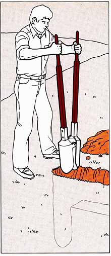
The top of the wall need not be level — timbers of different heights make an attractive effect—and you can, if you like, use “found” materials such as old pier pilings, telephone poles or even logs stripped of their bark. Make the basic trench for the timbers as deep as the wall is high, but at the corner posts and at every fifth timber, use a posthole digger (right) to double the depth of the trench. For example, a wall 18 inches high calls for a trench 18 inches deep, but the corner and every fifth timber should be sunk in holes that are 36 inches deep.
Once the trench is dug, you need only insert the timbers one by one, starting at a corner, spike them together, fill the trench with dirt and use a hand tamper to compact the fill.
1. Digging the trenches. Lay out the face of the trench with a series of stakes driven every two feet and dig a basic trench to the depth of the wall height; then, straddling the corner of the trench, use a posthole digger to make a hole for a single timber twice the depth of the basic trench. When you have laid and pinned four timbers by the method shown below, use the posthole digger to make another deep hole, and repeat the procedure for every fifth timber.
2. Pinning the wall together. Set the corner post in its hole, set a post next to it, and drill two horizontal 3/8-inch holes, one above grade and one below, through one timber and into the next. Drive 3/8-inch spikes into the holes. Repeat the procedure on every post, staggering the levels of the drilled holes so that spikes do not collide.
Designing and Building a Free-FormGarden Pool
Few additions lend more charm to a gar den than a sunken pool. While prefabricated pools of plastic, fiberglass or metal resist frost damage and are easy to install, they come in a limited variety of shapes and sizes. Working with concrete, you can pick the size, shape and depth that suit you—for a water garden, a fish pond or a wading pool or for a decorative set ting for a fountain or waterfall. In areas of moderate frost, the reinforced bowl shape of the pool below will keep the possibility of frost damage to a minimum, and it's suitable for small to medium sizes, up to about 7,000 gallons’ capacity.
Choose a site free of large rocks or tree roots—to make sure, dig a series of test holes about 2½ feet deep with a post-hole digger. A level site is easiest to work with, but you may prefer a slight grade— perhaps to provide a gravity drain at the low end of the pool, or to incorporate a waterfall on the high side, If you do build on a slope, you will have to provide a concrete lip on the downhill side of the pool at the same level as the upper lip, and you may have to grade the ground on the lower side to make the built-up lip less obtrusive.
When you are satisfied with the location, prepare a scale drawing of the pool and take it with you to your building supplier for an estimate of concrete and reinforcing materials you will need. A garden pool requires a fairly stiff mixture of concrete, consisting of 1 part portland cement, 2 parts sand and 3 parts washed stones or small aggregate, plus an additive to aid the formation of tiny air bubbles that make the mix easier to pour and make the finished concrete more resistant to freezing and cracking. To allow for errors, purchase about 10 per cent more of each ingredient than your estimated needs—check with the supplier to be sure you will be able to return any unopened bags. If your plan calls for more than 1 cubic yard of concrete—the pool shown here requires about 2½ cubic yards of mix—you will need to rent a mixer you can set up at the work area.
You will also need overlapping sections of 10-gauge 6 x 6 wire mesh to line the bottom and sides of the pool, and ½- inch steel reinforcing rods, or rebar, to strengthen the concrete lip. Since the re bar should be cut to size on the job, plan on renting a rebar cutter.
On the job itself, you will be handling several tons of earth and concrete; enlist a helper or two before excavating or pouring. Dig a hole that forms an exact bowl-shaped mold for the concrete; the bowl must rest on a base of undisturbed soil, and for that reason you should not refill any part of the hole with dug-out soil: that could cause the concrete to settle unevenly and possibly crack.
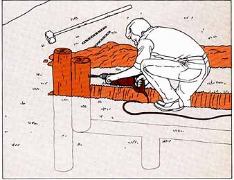
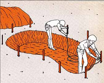
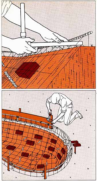
1. Drawing the pool. Outline the pool with a rope or length
of garden hose and transfer the outline to the ground by squirting chalk
dust over the rope or hose from a squeeze bottle. Dig the hole 5 inches
larger in every dimension to allow for the thickness of the concrete, and bevel the sides of the hole to a 45° angle.
For the construction method described here, make the hole no more than 30 inches deep.
2. Leveling the lip. Drive 18-inch stakes at 3-foot intervals around the rim of the pool, 6 inches out from the edge; then place one end of a water- level hose against a stake on the upper slope, with the water in the hose 5 inches above the ground. Have a helper move the other end of the hose around the pool, marking each of the stakes at the same level.
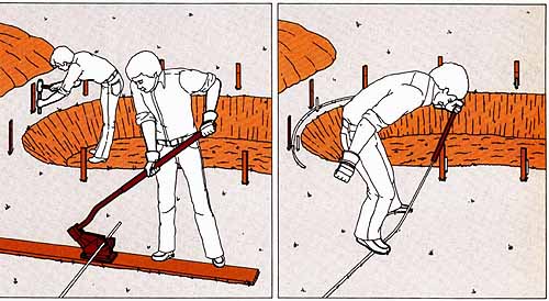
3. Installing vertical support rods. Cut 3/8-inch reinforcing rods into 20-inch lengths by inserting the bar into a rented cutter mounted on a 2-by- 10 board and , standing on the board, pushing downward on the cutter handle. Pound the rods into the ground halfway between the stakes and the edge of the hole, bringing their tops 2 inches below the level marks on the stakes.
4. Bending the horizontal rods. To shape reinforcing rods to the curvature of the pool, slide a length of rigid plumbing pipe over the end of a rod, step on the rod and gradually pull the pipe to ward you. As you bend the rods, lay them in position next to the vertical support rods, overlap ping adjacent ends by 12 inches. After bending the last rod, trim it to size with the cutter.
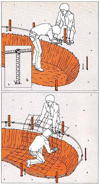
5. Making the frame. Hold an 8-foot length of the bent reinforcing rod to the tops of three ad joining vertical rods; if the bent rod does not span all three, drive an additional vertical rod near the end of the horizontal one. Secure the bent rods to one another and to the vertical rods with short strips of tie wire (inset).
6. Fitting the mesh. Bend sheets of 10-gauge 6 x 6 wire reinforcing mesh to cover the bottom and sides of the pool and extend 3 inches be yond the reinforcing-rod rim. Overlap the sheets a few inches, and trim the outer edges with wire cutters to fit them to the shape of the pool. When the pool and its rim are completely covered, lift the mesh one sheet at a time and place bricks on the dirt, flat side up and spaced 1 foot apart. Secure overlaps between sheets with tie wire, then bend the mesh edges over the frame of reinforcing bar and tie them to the frame. To provide a depth gauge for the concrete lining, drive 15-inch pegs cut from reinforcing bar into the bottom and sides of the pool at 2-foot intervals so that they protrude 5 inches.
7. Fitting an overflow pipe. Join two 1-foot lengths of 3 plastic plumbing pipe to a 90-degree elbow, and insert one end through the mesh at ground level with the elbow 5 inches inside the mesh at the rim of the pool. Turn the assembly so that the inside end points straight up. To hold the overflow pipe steady while the concrete is poured, wedge it in place with bricks or rocks and secure it to the mesh with tie wire.
8. Making the forms. Cut strips of ½-inch hard-board 6 feet long and tapered to meet the level marks on the stakes; nail the strips to the in sides of the stakes with their top edges at the level marks on the stakes. Notch the hardboard to fit around the overflow pipe. Brush vegetable oil onto the inner surfaces of the hardboard strips to prevent them from sticking to the concrete.
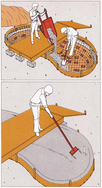
9. Pouring the concrete. To support your wheel barrow while pouring, prop a platform made of cross-braced 2-by-6 boards and 3 ply wood, on cement blocks. Have a helper, standing in the pool on two scraps of plywood, spread the concrete around the bottom and up the sides until the mix is even with the peg tops.
10. Floating and troweling. Smooth the concrete with a long-handled wood float made with a 6-foot length of 2-by-2 cut at a 600 angle at one end and nailed to a 1-foot length of 1-by-6 board. Rub the concrete lightly and evenly until all the depth pegs are just below the surface. Shape and smooth the lip with a mason’s trowel.
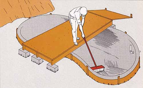
11. Finishing the surface. Draw a stiff-bristled broom across the concrete to roughen and ridge the surfaces. If the concrete sets so quickly that the bristles leave little or no impression, spray it lightly with water to soften it temporarily. When the concrete has cured—in about 3 days—coat the surface with waterproof paint or a pool sealer and plug any gaps around the overflow pipe with polyurethane caulking. Saw the top of the overflow pipe off just below the pool rim; cover the pipe intake with a disk of fiberglass screening secured with a plastic hose clamp.
- The Finishing Touches –
Stores that stock equipment for swimming pools, gardens or aquariums sell a wide variety of materials to help you keep your pool looking distinctively attractive. Among them:
+ Plastic, vinyl or silicone paints are available in numerous colors—including black, which, to the surprise of some people, is the choice of most landscape designers and offers many advantages, It looks natural and gives an illusion of great depth. And because it absorbs heat, it helps to protect fish and plants from the shock of a sudden frost or from cold weather.
+ Pools holding more than 500 gallons should be equipped with an electric re circulating pump to aerate the water and prevent it from becoming stagnant. There are two kinds of pumps: the submersible type, placed in the pool and hidden beneath plants or a stone shelf; and the non-submersible type, generally placed in a shallow well-hole next to the pool. Pumps are rated by the number of gallons of water they can circulate in one hour; a unit with a rating of 170 to 300 gallons per hour (referred to as GPH by pump manufacturers) is adequate for most pools.
+ If you plan to use your pool as a fish pond or a setting for water plants, buy a powdered neutralizing agent from a masonry dealer or garden-supply store. Mixed with water, the powder becomes a sealer that neutralizes the harmful alkalis in freshly cured concrete. The alkalis can also be neutralized by filling the pool with a solution of 1 quart of vinegar to every 100 gallons of water. Leave the solution in the pool for three days, drain it off and scrub the pool with a stiff brush. After rinsing, refill with fresh water and plant water lilies in pots set on the pool bottom, or water hyacinths that float on the surface. Lotus, Azolla and Elodea also are often used.
+ Algae growth, a recurrent problem in still pools, can be curbed by such scavengers as snails, turtles and frogs; an efficient way to control insect pests, such as mosquitoes, that could thrive in the pool’s still water is to stock the pool with goldfish.