| HOME | Troubleshooting | DIY Tips |
|
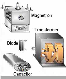
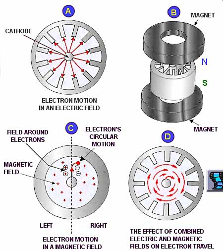
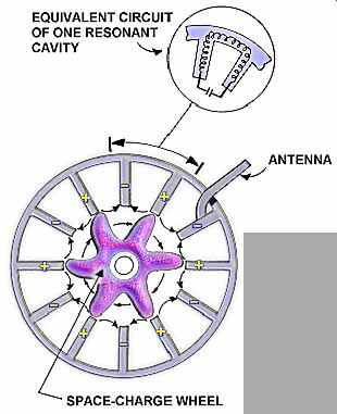
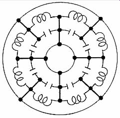
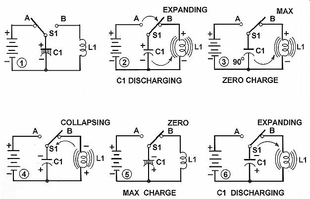
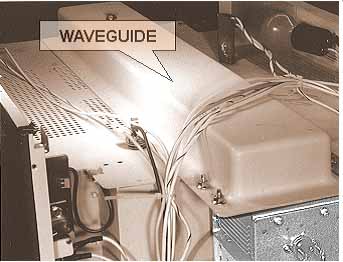
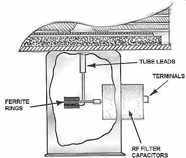
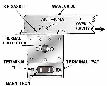
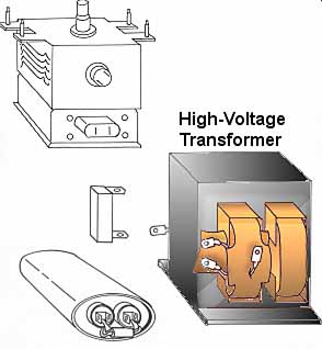
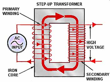
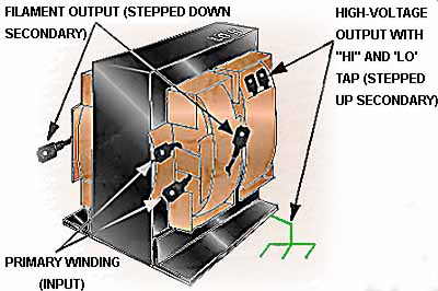
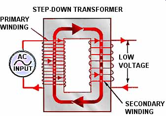
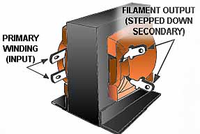
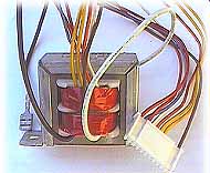
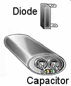
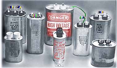
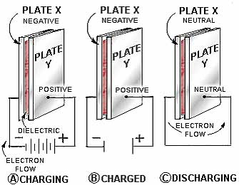
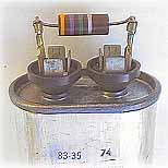
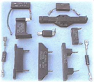
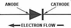
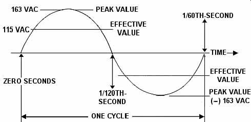
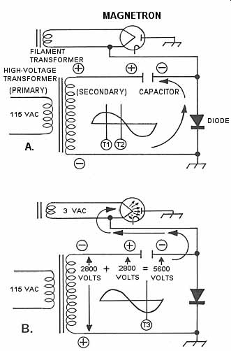
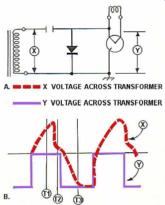
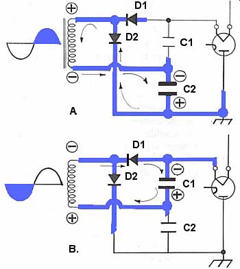
INTRODUCTION The purpose of the high-voltage system (Ill. 1) is to generate microwave energy. The heart of the microwave oven, it steps up AC line voltage to high voltage, changes the high AC voltage to an even higher DC voltage, and then converts the DC power to RF energy. The nucleus of the high-voltage system is the MAGNETRON TUBE. MAGNETRON TUBE The magnetron tube is a diode-type electron tube that is used to produce the required 2450 MHz of microwave energy. It is classed as a diode because it has no grid, as does an ordinary electron tube. A magnetic field imposed on the space between the anode (plate) and the cathode serves as the grid. Ill. 2 is a sectional view of a typical magnetron tube. While the outer configurations of different type magnetrons will vary by make and model, the basic internal structures are the same. These are the anode, the filament/cathode, the antenna and the magnets. The ANODE (or plate) is a hollow cylinder of iron from which an even number of anode vanes extend inward, as shown in Ill. 4 and Ill. 4A. The open trapezoidal shaped areas between each of the vanes are resonant cavities, which serve as tuned circuits, and determine the output frequency of the tube. The anode operates in such a way that alternate segments must be connected, or strapped, so that each segment is opposite in polarity to the segment on either side. In effect, the cavities are connected in parallel with regard to the output. This will be become easier to understand as the description of operation is considered. The FILAMENT (also referred to as the heater), which also serves as the CATHODE of the tube, is located in the center of the magnetron and is supported by the large and rigid filament leads which are carefully sealed into the tube and shielded. The ANTENNA, a probe or loop connected to the anode and extending into one of the tuned cavities, is coupled to the waveguide into which it transmits the RF energy. The other parts of the magnetron assembly may vary in their relative positions, size and shape, depending on the manufacturer. To keep the following explanation of operation as simple as possible, only the terms that are not self-explanatory as to their purpose will be elaborated on. The MAGNETIC FIELD is provided by strong permanent magnets, which are mounted around the magnetron so that the magnetic field is parallel with the axis of the cathode. Ill. 1 Typical high-voltage system. BASIC MAGNETRON OPERATION The theory of magnetron operation is based on the motion of electrons under the combined influence of electric and magnetic fields. For the tube to operate, electrons must flow from the cathode to the anode. There are two basic laws that govern this motion: 1. The force exerted by an electric field on an electron is proportional to the strength of the field. Electrons tend to move from a point of negative potential toward a positive potential. Ill. 4A shows the uniform and direct movement of the electrons in an electric field, from the negative cathode to the positive anode, with no magnetic field present. 2. The force exerted on an electron in a magnetic field is at right angles to both the field itself, and to the path of the electron. The direction of the force is such that the electron proceeds to the anode in a curve rather than a direct path. Effect of the Magnetic Field Ill. 4 Electron motion in a magnetron tube. In Ill. 4B two permanent magnets are added above and below the tube structure. In Ill. 4C, assume the upper magnet is a North Pole and you are viewing from that position. The lower, South Pole magnet, is located underneath the Figure so that the magnetic field appears to be going right through the paper. Just as electrons flowing through a solid wire cause a magnetic field to build up around the wire, so an electron moving through space tends to build up a magnetic field around itself. On one side (left) of the electron's path, this self-induced magnetic field adds to the permanent magnetic field surrounding it. On the other side of its path, it has the opposite effect of subtracting from the permanent magnetic field. The magnetic field on the right side is therefore weakened, and the electron's trajectory bends in that direction, resulting in a circular motion of travel to the anode. The process begins with a low voltage being applied to the filament which causes it to heat up (filament voltage is usually 3 to 4 VAC, depending on the make and model). Remember, in a magnetron, the filament is also the cathode. The temperature rise causes increased molecular activity within the cathode to the extent that it begins to "boil" off or emit electrons. Electrons leaving the surface of a heated filament wire might be compared to molecules that leave the surface of boiling water in the form of steam. The electrons, however, do not evaporate. They float just off the surface of the cathode, waiting for some momentum. Electrons, being negative charges, are strongly repelled by like negative charges. So this floating cloud of electrons would be repelled away from a negatively charged cathode. The distance and velocity of their travel would increase with the intensity of the applied negative charge. Momentum is thus provided by a negative 4000 volts DC, which is produced by means of the high-voltage transformer and the doubler action of the diode and capacitor. (4000 VDC is an average; the actual voltage varies with make and model.) A negative 4000-volt potential on the cathode puts a corresponding positive 4000-volt potential on the anode. Needless to say, the electrons leave the vicinity of the cathode with vigor, and accelerate straight toward the positive an ode-But not for long. As the electrons hasten toward their objective, they encounter the powerful magnetic field. The effect of the two permanent magnets, positioned so that their magnetic field is applied parallel to the cathode, tends to deflect the speeding electrons away from the anode as described earlier. Ill. 4D shows the effect of the magnetic field on the path of the electrons; instead of traveling straight to the anode, they curve to a path at almost right angles to their previous direction, resulting in an expanding circular orbit around the cathode that eventually reaches the anode. The whirling cloud of electrons, influenced by the high voltage and the strong magnetic field, form a rotating pattern that resembles spokes in a spinning wheel (Ill. g-5). The interaction of this rotating space charge wheel with the configuration of the surface of the anode produces an alternating current flow in the resonant cavities of the anode. This is explained as follows: as a "spoke" of electrons approaches an anode vane (or the segment between two cavities), it induces a positive charge in that segment. As the electrons pass, the positive charge diminishes in the first segment while another positive charge is being induced in the next segment. Current is induced because the physical structure of the anode forms the equivalent of a series of high-Q resonant inductive capacitive (LC) circuits. The effect of the strapping of alternate segments (mentioned earlier) is to connect the LC circuits in parallel (Ill. 6). Ill. 5 Electrons form a rotating pattern. Resonant Circuits A resonant circuit consists of a coil and capacitor connected in parallel and produces high frequency current flow as next explained in Ill. 7. In step 1, the battery (which represents the energy being supplied to the circuit by the passing "spoke" of electrons) will charge up capacitor C1. In step 2, when S1 is switched to position "B" (which represents the electrons having passed by and there fore no longer inducing a charge) the capacitor discharges through coil L1. The current flow through the coil causes a magnetic field to develop around the coil, which is accompanied by an internally induced voltage of a polarity that opposes the capacitor discharge. In step 3, C1 has completely discharged and the energy is now stored in the magnetic field that surrounds the coil. In step 4, the magnetic field begins to collapse around the coil causing the voltage induced within it to change polarity. This tends to keep the current flowing in the original direction, which at step 5, charges the capacitor with a polarity opposite from its original charge. Consequently, at step 6 the capacitor again discharges through the coil, although in an opposite direction, starting the process all over. This seesaw action can produce extremely high oscillations, the frequencies of which are determined by the values of the capacitance and the inductance. In each resonant cavity of a magnetron tube, the walls act as an inductor (or a coil), and the parallel sides of the opening form the plates of a capacitor (refer back to Ill. 5). Since the amount of inductance and capacitance is very small, the frequency of the alternating current is very high. The electromagnetic oscillations produced in the resonant cavities are intercepted by the antenna, which then couples the energy into a waveguide. Ill. 6 Equivalent circuit of cavities in parallel because of strapping. Ill. 7 Basic operation of a resonant circuit. The Waveguide Microwave energy cannot travel through a solid conductor, so the antenna radiates the RF power into a waveguide. The waveguide, a hollow metal tube (Ill. 8), transports the microwave energy into the oven cavity. Most microwave ovens use a rectangular shaped waveguide, through which the waves of energy travel by reflecting from side to side in a zigzag pattern. Ill. 8 The waveguide is a hollow rectangular tube. RF Capacitors In order to prevent small amounts of RF current from backfeeding down the magnetron tube filament leads, which would cause excessive radio and television interference, by-pass (or RF) capacitors and ferrite rings are added to the magnetron assembly (Ill. 9). By-pass capacitors filter off any backfeeding current to ground. The ferrite rings are magnetic and oppose high-frequency current flow. Cooling Fins Other features of the magnetron structure are the cooling fins, which dissipate the tremendous heat generated by an oscillating magnetron, usually maintaining an operating temperature of about 260º F. (86º C). Proper Phasing Located near the filament terminals are the designations "F" and "FA". These insure that proper phasing is maintained when reconnecting the filament and high-voltage leads. Proper phase relationships, or polarities, within the high-voltage circuits are important. Failure to observe these relationships when reconnecting wires can put high voltage components out of phase with each other. This can cause such symptoms as intermittent "popping," and even the premature failure of the components. Ill. 9 RF capacitors and ferrite rings in a magnetron tube. Magnetron Life Expectancy The typical life of a magnetron tube is approximately 2000 hours of operation. Some factors that can diminish the life of a magnetron are: (1) no-load operation, (2) operating with too much metal in the cooking cavity, (3) line voltage consistently too low or too high, (4) improper phasing, (5) improper installation or removal, (6) replacing associated high-voltage components with substitutes that are in compatible with the system design, (7) continual operation at the upper limit of its heat tolerance due to inadequate air circulation, (8) obstruction in the waveguide, (9) failed stirrer operation. Coverage of magnetron failure modes, testing, and replacement procedures begins in a later discussion. TRANSFORMERS In microwave oven circuits, transformers serve two functions: either they in crease (step up) voltage, or they de crease (step down) voltage. The first type of transformer to be considered will be the step-up transformer. Ill. 10 Magnetron terminal designations for proper phasing. High-Voltage Transformer Ill. 11 High-voltage transformer in a typical high-voltage system. The high-voltage transformer (also referred to as power or plate transformer) is of the step-up variety. With a typical voltage of 120 VAC (± 10%) applied to the primary winding (some commercial units are designed to operate with a primary voltage of 208 to 240 VAC), the transformer will step the voltage up to approximately 2400 VAC at the secondary output. Transformers work on a principle called mutual induction. It is the physical characteristics of the transformer combined with an input of alternating current that produces this process. A simple step-up transformer consists of an open square or frame of iron called the core. Coils of insulated wire are wound around the two opposite sides of the core forming two separate coils (Ill. 12). As illustrated in Ill. 12, when alternating current is applied to the primary winding, the changing current flow produces a magnetic field within the iron core that reverses with each alternation of the applied current. Since a conductor moving through magnetic lines of force will have a voltage generated within it, it follows that a stationary conductor placed within a changing magnetic field would also have a voltage generated or induced within it. Such is the case with the secondary winding. If the two ends of the secondary winding are connected together, an induced alternating current will flow. While the frequency of the current flow in the secondary is the same as that of the primary, the strength of the induced voltage depends on the ratio of the number of turns in the secondary winding to the number of turns in the primary winding. For example, a primary of 8 turns and a secondary of 16 turns would be a ratio of 1 to 2. At that ratio, 120 VAC applied to the primary would produce 240 VAC at the secondary. Transformer design and construction depend on the way in which it will be used. Microwave ovens use a saturated core type, in which the core operates at magnetic saturation. Thus, any variation in the primary, such as a voltage drop or surge will not affect the constant output of the secondary. Whereas all high-voltage transformers used in microwave ovens have at least one secondary terminal (or high-voltage tap), some have two or more high-voltage outputs (Ill. 13). The high-voltage terminal labeled "HI" utilizes the full number of turns in the secondary coil and thus yields the maximum high-voltage output. By tapping into the coil at a point having fewer turns, the terminal designated as "LO" utilizes only part of the secondary winding. Thus, output at the "LO" tap is correspondingly less than that of the "HI" tap. While these additional taps are provided to compensate for variations in capacitor values, they afford other benefits also: The weakening RF out put of an aging magnetron tube can be boosted by changing the high voltage output from the "LO" to the "HI" tap. A different tap selection can also improve an unsatisfactory RF energy cooking pattern. Additional primary and secondary terminals are also provided on the transformers in certain models that enable conversion of the power supply operating frequency. These models can be converted to operate on either 60 Hz or 50 Hz. The pertinent conversion instructions are usually affixed to the inside of the outer cover or side panel. See __ for an example of a common method of frequency con version, which involves the high-voltage capacitor. Ill. 12 Simple step-up transformer. Ill. 13 Typical High-Voltage (Power) Transformer. Ill. 14 Simple step-down transformer. Filament Transformer Secondly, the filament transformer is of the step down variety (Ill. 14). A voltage of 120 volts applied to the primary winding of the filament transformer is stepped down to approximately 3 VAC (the actual filament volt age varies with different models). This low voltage, high-current output of the filament transformer is used to heat the magnetron filament. In an increasing number of micro wave ovens, the step-down windings of the filament transformer are incorporated within the structure of the high-voltage transformer, as in Ill. 13. This means that from a common primary, voltage is stepped up in one secondary winding, and stepped down in the other. In other cases, the filament transformer is a separate, smaller unit. (Ill. 15 shows a typical filament transformer.) Ill. 15 Typical filament transformer. Even smaller, in size and output, are the low-voltage (or control) transformers (Ill. 16). These usually have several secondary taps, which provide an appropriate selection of control voltages as required by the various electronic control panels. These control transformers are not part of the high-voltage section; rather they are a component of the control section and thus covered in detail in __. The transformers discussed here are common to all micro wave ovens, with the exception of the low-voltage transformer, which is not required in models that use mechanical timers and controllers. Other types of transformers, their applications and functions, will be explained as the need arises. Transformer testing procedures and failure modes, with related symptoms, are outlined in __. Ill. 16 Typical low-voltage transformer. THE HIGH-VOLTAGE CAPACITOR AND DIODE-THE VOLTAGE-DOUBLER CIRCUIT In most domestic models of microwave ovens, the high voltage necessary to operate the magnetron is generated by the action of a diode and capacitor (Ill. 17) combination that effectively doubles the voltage, and is aptly called a voltage doubler. A step-up transformer alone could pro duce the required high voltage, but it would be immense in size, weight, and expense. The doubler circuit allows for the use of a much smaller high-voltage transformer by doubling the transformer's al ready-stepped-up output voltage. Thus, the required high voltage is obtained from smaller, lighter, and less expensive components. While most models today use a half-wave doubler circuit, many commercial models still in the field use a full-wave voltage doubler circuit. Important to the understanding of a voltage doubler circuit is a basic knowledge of its two components, the capacitor and the diode. Ill. 17 The capacitor and diode form a voltage doubler. The High-Voltage Capacitor Ill. 18 Typical high-voltage capacitors. Essentially, a capacitor is made up of two metal plates separated by an insulator or dielectric. Oil usually serves as the dielectric in micro wave oven capacitors. Capacity means a maximum ability to hold or contain, so a capacitor may be thought of as a device that temporarily stores electrons. This energy is stored in the form of a charge. The amount of capacitance depends on the surface area of the metal plates, the distance between the plates, and the type of dielectric material. Capacitance is measured in farads. However, a capacitor with a value of 1 farad would be of enormous dimensions, so practical units of capacitance are more commonly referred to as microfarads. Ill. 18 shows an array of capacitors that are typically used in the voltage doubler circuits of microwave ovens. This application calls for capacitance values ranging from 0.7 to 1.5 microfarads, depending on the make and model. Just as when blowing up a balloon the air does not pass through the balloon, but is stored inside until released, so too with electrons flowing into a capacitor; they do not flow through the capacitor, but rather into and out of it at the frequency of the applied voltage. Ill. 19 depicts a capacitor in its simplest form. If a voltage is applied as shown in part (A), electrons will flow onto plate "X" making it negative. Electrons cannot flow through the dielectric material between the plates, so plate "Y" becomes positive with respect to plate "X." If the voltage source is now removed, as shown in part (B), the capacitor becomes a source of potential energy, similar to a charged battery. By allowing the capacitor to discharge through an external circuit, as shown in part (C), the stored energy may be utilized and the potential difference between the two plates becomes zero. If the polarity of the voltage source is reversed, then re-connected, the same sequence of action would occur except that corresponding polarities would be reversed. Unless high-voltage capacitors are provided with a discharge path, they will retain a significant charge even after the unit is shut down and unplugged. For that reason many manufacturers add a bleeder resistor, either externally (Ill. 20) or internally. The sole purpose of this very high ohm resistor is to protect servicing personnel by allowing any high electrical charge that may be present to dissipate or bleed off within 20 to 30 seconds after the oven is shut down. Whether or not you trust the bleeder resistor is up to you. However, if it is open, and if your finger provides the discharge path, your reflex action could make you the bleeder. Ill. 20 Capacitor with external bleeder resistor. A blower capacitor is found in some commercial microwave ovens (i.e., Litton). This comparatively smaller capacitor is connected across the start and run windings of the motor, and provides a constant phase shift that ensures maximum speed with minimum current draw. Also employed by some commercial units is a filament capacitor. This capacitor provides a degree of voltage stabilization for the filament transformer to ensure a constant secondary voltage in the event that variations or fluctuations of the source voltage should occur. Many capacitors are manufactured with a + 10% (approximate) tolerance in capacitance. These capacitors are color coded with a paint dot to indicate their actual value. A capacitor rated at 1.0 Mfd. with a white or black dot would actually be slightly lower than the rated 1.0 Mfd. Correspondingly, a red or yellow dot would indicate a slightly higher value. In some cases, there are variations from the above characteristics, as well as in the specific application. One such variant is the dual-rated capacitor used to facilitate the conversion of the power supply operating frequency. This feature allows models so equipped to be operated at 50 Hz or 60 Hz, depending on the line voltage frequency of the country in which it is to be used. Later, we will discuss a typical frequency conversion procedure. The question of capacitor interchangeability depends mainly on the value (in microfarads) and the voltage rating. The physical size may also be a limiting factor. And, of course, a capacitor with an internal diode cannot be substituted for a capacitor designed for use with an external diode, and vice versa. Various types of failures, associated symptoms and testing procedures for the high-voltage capacitor are covered in ab upcoming discussion. The High-Voltage Diode A diode (which is also called a rectifier because it is used to convert or rectify alternating current into direct current) is a device that will pass current in one direction only. In one direction, a diode acts as a conductor, while in the other direction it blocks current flow as an insulator. There are many types of diodes, available in all shapes and sizes, from tiny ones about the size of a pinhead to the larger type that are used in microwave ovens. Ill. 21 shows the variety of diodes used in commercial and residential microwave ovens. In many cases, compatibility in size, mounting con figurations and voltage-current ratings, allow diodes to be interchanged as suitable replacements. A word of caution though: due to different operating characteristics, care must be exercised when substituting one diode for another. Other than the technical documentation on a given diode, or when approved by the respective manufacturer, the only means to determine interchangeability is physical size, terminal and mounting arrangement, and experience. If an interchanged diode becomes too hot to comfortably touch after two to three minutes of operation, it is not an adequate substitute. Ill. 21 Typical high-voltage diodes Ill. 22 Schematic symbol for a diode. Ill. 22 shows the schematic symbol for a diode. Current flow is always from the cathode to the anode, or against the direction of the arrow. There is a logical reason for this seemingly illogical symbolism, but it is confusing and irrelevant to the purpose of this explanation. Just re member that the arrow points in the opposite direction to the current flow, and in a half-wave voltage doubler the arrow always points to chassis ground. Occasionally reference is made to a stacked diode. A stacked diode is comprised of a series .of diodes encased within one housing and internally connected so as to better handle higher back voltage. In some voltage-doubler systems, a varistor is employed (either externally or internally) across the high-voltage diode. The varistor has a very high resistance at normal voltages. How ever, if the voltage across the diode increases due to a surge or spike, the varistor's resistance rapidly decreases providing a shunt path to ground for the potentially damaging surge. (See __ for detailed information on voltage protection devices.) Also found across the diode, de pending on the model, may be a bleeder resistor or a bleeder-varistor combination. Types of diode failures to look for, with the accompanying symptoms and methods of testing, are discussed later. THE HIGH-VOLTAGE CIRCUIT-VOLTAGE DOUBLER OPERATION To effectively analyze a voltage-doubler circuit, it is first necessary to understand the difference between effective voltage and peak voltage. Measured with a common voltmeter, the voltage in the standard receptacle is 115 VAC (+ 10%). The actual voltage alternates through one complete cycle every 60th of a second as shown in the sine wave of Ill. 23. Since the voltage is continuously varying, the value read on the voltmeter is only the effective value of this voltage. The peak value that the sine wave reaches is 1.414 times the effective value. Therefore, the peak volt age from a standard receptacle would be: Peak voltage = 1.414 X 115 VAC = 163 VAC Knowing peak values and their relationship to effective values is important to understanding the operation of a voltage-doubler circuit. Voltage-doubler circuits are fed with the stepped up AC voltage from the transformer's secondary winding. Typically, a transformer would step up 115 volts to 2000 volts, which would have an approximate peak value of 2800 volts. We will use this value in analyzing the operating sequence of a voltage doubler. Please note that the values of voltages shown are peak, no-load, theoretical values. The actual effective values will be considered after the explanation. Ill. 23 60 HZ sine wave. Half-Wave Voltage Doubter Refer to Ill. 24A. During the first positive half-cycle, which is designated on the sine wave graph as "T1," the voltage from the transformer increases accordingly with the polarity shown. The current flows in the direction of the arrow, charging the capacitor through the diode. During the capacitor charging time there is no voltage to the magnetron because the current takes the course of least resistance. In other words, rather than take a path through ground and up to the plate of the magnetron, the current swings up through the diode. The voltage across the capacitor will rise with the transformer secondary voltage to the maximum 2800 volts. As the transformer voltage begins to decrease from its maximum positive value (at time increment "T2" on the sine wave graph), the capacitor will try to discharge back through the diode. The diode, being a one way street, will not conduct in this direction and therefore blocks the discharge path, so the capacitor remains charged to the 2800 volts. At time "T3" ( Ill. 24B) the transformer secondary voltage swings into the negative half-cycle and increases in a negative direction to a negative (-) 2800 volts, with the polarities as shown. The transformer secondary and the charged capacitor are now essentially two energy sources in series. The 2800 volts across the transformer winding adds to the 2800 volts stored in the capacitor and the sum voltage of 5600 volts is applied to the magnetron cathode. Ill. 24 The operation of a half-wave voltage doubler. There are two fundamental characteristics of this 5600 volts output that should be noted. First, since a voltage doubler is also a rectifier, the output is a DC (direct current) voltage. Second, as waveform "Y" in Ill. 25B shows, the resulting output voltage that is applied to the magnetron tube is a pulsed DC. This is because the doubler generates an output only during the negative half-cycle of the transformer secondary voltage. This also means that the magnetron tube is actually pulsed on and off at a rate of 50 or 60 times a second, depending on the frequency of the line voltage. Full-Wave Voltage Doubler Ill. 25 Comparison of waveforms at the input and output of the voltage-doubler circuit. The full-wave doubler is simply an extension of the half-wave circuit just explained. This allows for a more simplified explanation. Ill. 26A shows the charging circuit during the positive half cycle of the transformer secondary voltage. With the polarities as shown, D2 will conduct allowing C2 to charge as indicated by the arrows. In Ill. 26B, the transformer voltage swings into the negative half cycle and the polarities are thus reversed. Now, current flows through D1, which causes C1 to charge up. The Diode (D2) does not conduct during this time be cause it is being reverse biased by the polarity of the transformer. The reverse bias effect on the diode (D2) causes it to oppose any current flow. When a diode is forward biased it freely conducts. When it is reverse biased, it presents a high resistance to current flow. Thus, in a full-wave voltage doubler the current flows to a different branch of the circuit each half cycle. Since capacitors C1 and C2 are connected in series, the voltages developed across them combine across the magnetron. Their combined voltage is two times the peak voltage of the transformer secondary. Usually, in actual practice, C1 and C2 are two capacitors in one. This type of capacitor is generally called a dual-rating capacitor and consists of two capacitors connected and incorporated in one case. The same is sometimes true also with diodes D1 and D2. Ill. 26 The operation of a full-wave voltage doubler. Full-wave doublers, although more efficient than half-wave doublers, are not as common in microwave ovens as they once were. Early commercial units used full-wave voltage doublers to drive a single 1000-watt magnetron. However, this design has, by and large, been phased out in favor of a system with two 700-watt magnetrons, each with their respective half-wave voltage doubler systems. These dual-magnetron systems have, in fact, proven to be more practical and of greater reliability than their single-tube predecessors. For example, if any portion of a single-tube unit fails, the entire system becomes inoperative. However, if the same disorder befalls a dual tube unit, the malfunctioning side can be disabled and oven operation continued at half power (which, to a restaurant owner, is better than nothing) until permanent repairs can be made. As mentioned earlier, the voltages used in the previous explanations were theoretical. Actually, the doubler circuit, which is inherently inefficient at best, is notably burdened when the magnetron goes into oscillation. The magnetron places a load on the circuit that may decrease the output of a voltage doubler by as much as 40 percent. A final word about high voltage: The circuits just described cannot be measured with a normal voltmeter. If you wish to measure the high voltage, a special high-voltage meter with special leads must be used. HIGH-VOLTAGE SAFETY PROCEDURES MUST BE CAREFULLY OBSERVED. However, microwave oven problems can be diagnosed just as, if not more, conclusively and certainly more safely without checking the high voltage. Therefore, MEASURING THE HIGH VOLTAGE IS NOT RECOMMENDED.
|