| Home | FAQ | Finishing | Sump Pumps | Foundations |
|
When a ceiling is added to a new living space, most people finish it with acoustical panels, acoustical tiles, or wallboard. If you wish to lower the ceiling, or if you need to cover pipes and ducts extending below the joists, a grid system of suspended panels is the best choice. If the ceiling will be left at its existing height, use either 1-foot- by-1-foot tiles or wallboard. Ceiling tiles are available in kits that provide metal strips and clips for support; alternatively, tiles can be stapled to a grid of wood furring strips nailed across joists. Wallboard is somewhat more difficult to install, but it's the least expensive ceiling material and the one most adaptable to different decorative treatments. Lighting and Wiring: Lighting a suspended-panel ceiling is easiest with a fluorescent fixture. For a tile or wallboard ceiling, use a recessed lamp (ref. 80). If you are replacing a ceiling light that was operated by a pull cord, you will need to add a wall switch. No matter what type of ceiling you plan to install, complete any extensive new wiring beforehand. Be aware that electrical connections must remain accessible when the ceiling is in place. In the case of suspended panels, all wiring above the ceiling will be readily reachable; but with tiles or wallboard, junction boxes that would be covered by the ceiling should be relocated. CAUTION: Before working with wiring, be sure the circuit is turned off at the service panel. If your house wiring is made of aluminum, have an electrician do all electrical work. TOOLS:
MATERIALS:
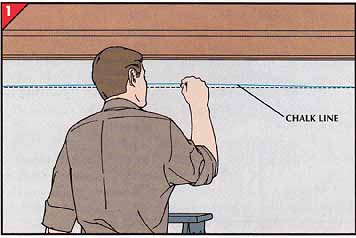
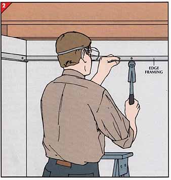
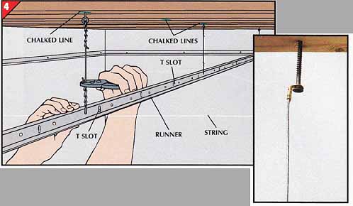
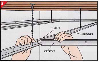
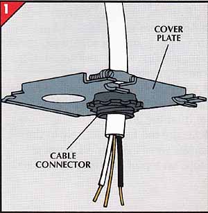
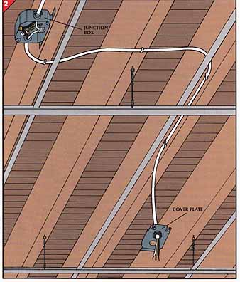
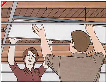
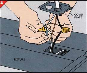
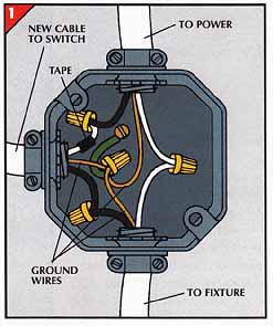
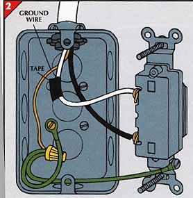
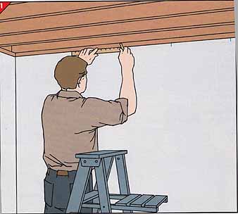
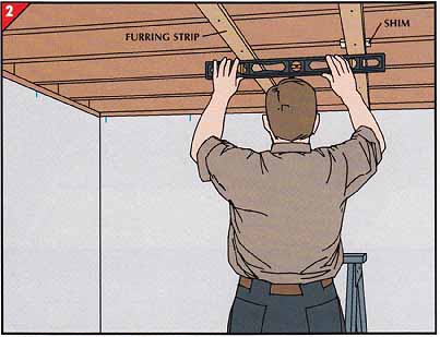
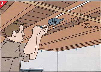
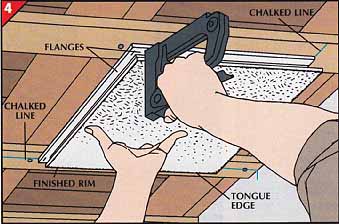
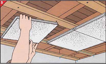
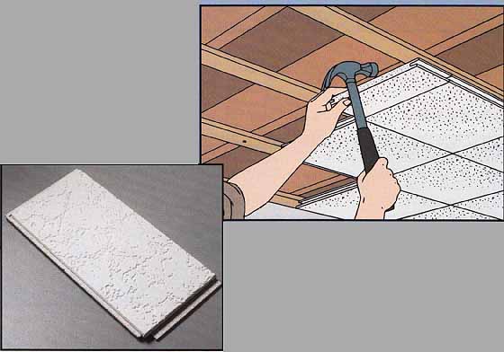
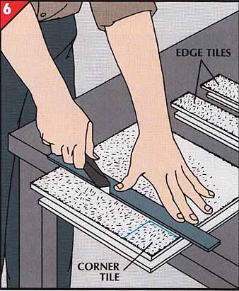
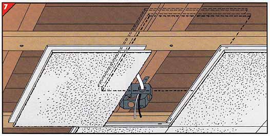
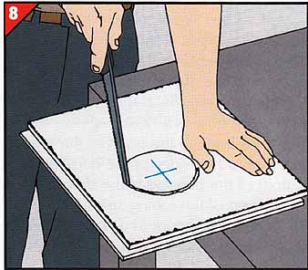
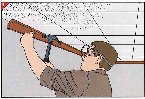
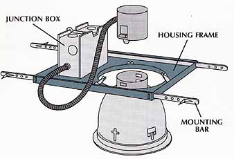
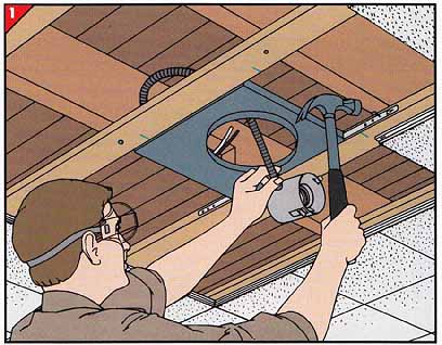
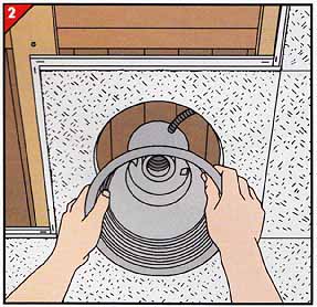
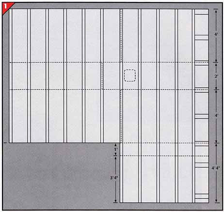
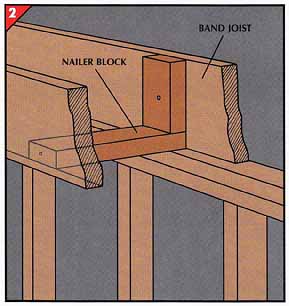
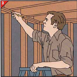
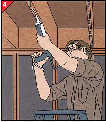
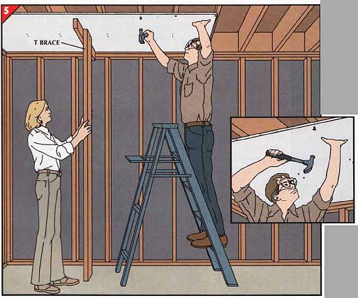
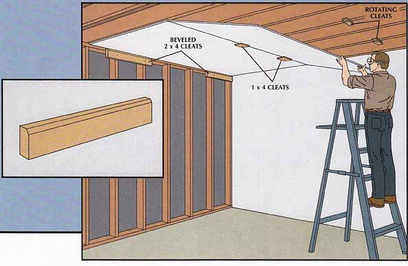
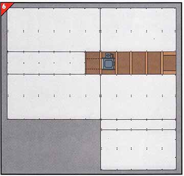
SAFETY FIRST: When working overhead or when nailing, protect your eyes with goggles. Note: Click provided links below for associated graphics. A System of Suspended Panels • Mark the intended ceiling height on the wall at all four corners of the room. Leave a minimum of 3 inches of space below the joists, increasing the space as necessary to clear ducts, pipes, or other obstructions and also to accommodate any light fixture. • Drive a nail at each corner mark. • Along each wall in turn, stretch a chalk line taut between nails, check it with a level, and snap it across the wall. • With a stud finder, locate studs behind the walls and mark them at the chalked lines. • Attach the ceiling grid’s L-shaped edge framing to studs along each wall with 1 ring-shank dry-wall nails or dry-wall screws. Where the ends of two strips of framing meet at a corner, lap one end over the other. If you must cut the framing strips, use tin snips. 3. Positioning runners and cross Ts. Runners always run perpendicular to joists; cross Ts, available in 2- or 4-foot lengths, run parallel and are supported by the runners. First, decide whether you want to install the 2- by 4- foot ceiling panels parallel or perpendicular to joists; this will determine how you measure each wall for the grid positions and what length cross Ts you must buy. The walls that the short ends of 2- by 4-foot panels abut—shown here as walls A and B—must be divided into 2-foot intervals, centered so that edge panels will be equal in size. Measure wall A from the midpoint to one of the corners. If the distance beyond the last 2-foot interval is 6 inches or more, mark the midpoints of walls A and B above the edge framing, then at 2-foot intervals on both sides of these marks for runners or cross Ts . If the distance is less than 6 inches, mark the walls a foot to one side or the other of the midpoints, then at 2-foot intervals for runners or cross Ts. To center the long dimension of the panels, use the same method to measure walls C and D, but mark them at 4-foot instead of 2-foot intervals. • To position the runners, snap chalked lines across the joists from the marks on the walls. • Along these chalked lines, attach a screw eye to the bottom edge of every other joist. Alternatively, purchase and attach adjustable hanger wires (photo graph), which can be raised or lowered by turning the screw. • If you are using screw eyes, insert a hanger wire in each eye, secure the wires by twisting them, and bend the free ends to 90-degree angles. • To ensure alignment of the cross T slots—which occur every 6 inches in the runners—stretch a string between two of the marks for a cross T on opposite walls, and hang the runners so that a on slot lies just above the string. • Add lengths of runners as needed, connecting them with their end tabs. Cut off any excess with tin snips, and set each runner in place with its ends resting on the edge framing. • Thread the hanger wires through the holes in the runners. • Level each runner by adjusting the hanger wires, then secure each wire by twisting it around itself. • Place cross Ts at the proper intervals and fit their ends into the slots in the runners. • Along the walls, rest the outer ends of the cross Ts on the edge framing. • Install panels in all the full- size openings in the grid by lifting each panel diagonally up through the framework, turning it to the horizontal, and resting its edges on the flanges of the runners and the cross Is. If you plan to add a light fixture (below), leave the grid openings surrounding the fixture empty in order to have ample room to work. • With a utility knife and a framing square, trim panels to fit the smaller spaces around the walls. Adding a Fluorescent Light Fixture 1. Connecting cable to cover plate. • Knock out one of the holes in the cover plate of the light fixture and insert the threaded end of a cable connector through from the top. • Attach the connector’s fastener and screw it tightly in place. • Cut 3 inches of sheathing off the end of a length of No. 14 plastic-sheathed cable and then peel off inch of insulation to bare the ends of the wires. • Slip the wires through the clamp on the cable connector until a little of the cable sheathing emerges from the other side. • Tighten the cable clamp to secure the cable. 2. Running cable to a junction box. • Turn off the electricity to the circuit at the service panel. • Cut the cable long enough to reach from the planned location of the light fixture to the junction box that holds the original ceiling light. • Unscrew the original fixture from the box, then disconnect and straight en the wires. • Remove a knockout hole from the junction box and fasten the new cable there with another cable connector. • Attach the ground wire from the cable to other ground wires and ground jumper wires in the box. • With wire caps, connect the wires— white to white and black to black. Then screw a cover plate to the box. • With insulated cable staples, fasten the cable to the joists to within 2 feet of the planned fixture location, but leave the plate-connected end dangling at the fixture position. • Attach two screw eyes to the joist above the fixture location, loop hanger wires through them, and secure the wires by twisting them. • With the help of a partner if necessary, angle the fixture into place and set it on the grid. • Secure the fixture loosely to the hanger wires through the holes or loops on top of the fixture’s housing. • Twist together and cap the white wire from the new light fixture and the white wire of the cable, then connect the black wires. • Push the wires into the opening on the fixture and then attach the cover plate. • From below, open the fixture and attach the cable ground wire to a grounding screw. • If the cable seems floppy, staple it at one more point near the fixture. Providing a Wall Switch 1. Connecting the junction box. • With the electricity to the circuit still turned off at the service panel, run No. 14 cable from the planned switch location on the wall near a door to the ceiling junction box, stapling it to the joists at 4-foot intervals and at bends. • Cut 3 inches of sheathing off both ends of the cable, then peel off inch of insulation to bare the wires. • Run the cable through a knockout hole in the ceiling box and secure it with a clamp. • Inside the box, recode the white wire from the new cable with black tape (to show that it's a hot wire in this application), twist it to the black wire from the power source, and cap the wires. • Join the black wire of the new cable to the black wire from the new light fixture. • Connect the white wire of the power source to the white wire of the cable from the fixture. • Twist the three bare ground wires together with the green wire leading to the ground screw, then cap them. • Cover the junction box with a plate. 2. Connecting the wall switch. • At the wall, install a standard outlet box. • Run the new cable into the box and tighten the clamp. • Recode the white wire with black tape to show that it's hot, then connect the black and white wires to the terminal screws of the switch. • Connect the bare ground wire of the cable with green wires leading to ground terminals on the switch and in the box. • Screw the switch to the box and attach the cover plate. Turn the power back on. An Acoustical the Surface 1. Planning the job. • At ceiling level, mark the centers of all four walls. • Measure from each mark to an adjacent corner. This distance will be a number of feet plus—in most cases—a fraction of a foot. If the fraction is less than 3 inches, move the center markers 6 inches right or left. • Mark 12-inch intervals from the markers to the adjoining walls. • To determine how many 1-by-3 furring strips you need, count the number of interval marks on one of the walls parallel to the joists. Add two extra strips, which will be nailed next to the walls. • Cut each strip the length of the walls perpendicular to the joists. • To estimate the number of tiles required, count the number of 12-inch intervals on one wall, then on its adjoining wall; add one to each of these figures and multiply them. • Tape a carpenter’s level to the narrow side of a straight 2-by-4 and check the joists lengthwise and crosswise to see how level a base they will provide. If they vary sharply, start by holding the first furring strip at right angles to the joists at their lowest level. • Center the ends of the strip between the pair of marks nearest the lowest point and attach the strip to the lowest joist with a 2 nail. • Using a level to guide you, shim the rest of the strip down from the higher joists. • Attach the next strip between pairs of marks, leveling it from the first one. • Continue to level and nail up strips in this way, and finish by attaching furring strips to the ends of the joists against the walls. 3. Adjusting ceiling fixtures. Any existing ceiling fixture that would interfere with a furring strip must be moved before the strip is nailed up. • Turn off the electric circuit, then remove the screws or nuts holding the fixture in place and pull it away from the ceiling box. • Detach the box from the joist, then reattach it to a joist so that it will be more or less in the middle of a tile, and its lower rim will be flush with the surface of the new ceiling. • Snap a chalked line down the center of the next-to-last furring strip on one side of the room. • Snap another line—intersecting the first at right angles— across the room between the pair of chalk marks nearest the corner. • Set the tile in the corner where the lines intersect, with the tongue edges toward the corner and the stapling flanges toward the center of the room. • Align the finished rims of the tile with the chalked marks, and staple the flanges to the furring strips on both sides. • Slide the tongue of the next tile into the groove on the stapled edge of the preceding tile. • Align the rims of the new tile with the chalked line and the rims of the preceding tile. • Staple the flanges of the new tile to the fur ring strips. PRO TIPS: Seating Tiles When installing tongue-and-groove tiles, use a spare tile to fit them into place with out damaging the flanges. Cut a tile in half and fit its tongue into the groove of a partially seated tile. Tap it lightly with a hammer to push the new tile into position. When the half tile becomes worn out, cut a fresh tile. • After installing three tiles, measure the distance from their finished rims to the walls at both ends of each tile. • Deduct inch from each measurement and use the results to mark the sizes for the corner and edge tiles. Place the marks so that you will be cutting off the tongue edges rather than the flange edges. • Draw lines between the marks and cut the tiles with a utility knife. • Slide the pieces into place, starting with the corner tile, and anchor them to the furring strips near the wall with 1 1/2-inch box nails. 7. Marking the site of an outlet box. • Tile as closely as possible to two adjacent sides of the outlet box of a ceiling fixture, then slip the tongue of a fresh tile into the groove of a tile al ready installed on one side of the box. • Slide the loose tile up to the box and mark the tongue of the tile at the point where it touches the midpoint of the rim of the box. Do not mark the face of the tile. • Slide the same tile up to the adjoining side of the box, and mark the point on the tile’s other tongue where it touches the mid point of the rim. 8. Cutting the hole. • Using a framing square, extend the marks on the back of the tile. The point at which these lines intersect on the back of the tile marks the center of the outlet box. • Transfer the center mark to the face of the tile. • Set a compass to a measure that's slightly less than the size of the box. • Draw a circle of this radius on the face of the tile, with the center of the circle at the point of intersection of the two lines. • Using a keyhole saw held with the blade pointed outward at a slight angle, make a beveled cut around the circle through the face to the back of the tile. • Staple the tile in place around the box as described in Step 5, then reattach the fixture and turn the circuit back on. • After installing all the tiles, use the procedure shown earlier to miter-joint 1 cove molding to cover the junction between walls and ceiling. • Attach the molding as described earlier. A Recessed Light Fixture Buy a recessed fixture that's thermally protected to prevent fires. Choose one that has an attached junction box in which fixture wires can be connected to the electric cable; with this feature, you will not need to install a separate outlet on the joist above the fixture. If there was a previous fixture, you can connect the new fixture to the old circuit; other wise, extend the wiring from a nearby junction box to the de sired location of the new fixture. 1. Installing the housing frame. • Hold in place, but don't fasten, the tile that will surround the fixture. • Mark its boundaries, remove it, and position the housing frame of the fixture between the furring strips so the center of the opening in the frame will be more or less above the center of the tile. • Fasten the housing frame to the edges of ad joining furring strips by driving nails into the fur ring strips through the holes in the mounting bars attached to two sides of the housing frame. The bottom of the housing frame should be flush with the bottom of the furring strips. • Connect the fixture to a power source by joining the wires as described for a fluorescent fixture on above. 2. Completing the installation. • Using the method described in Steps 7 and 8, determine the location of the center of the hole you will cut in the tile to accommodate the round receptacle in the bottom of the housing frame. • Cut the hole and install the tile. • Snap the reflector-trim unit into the socket holder, insert a bulb of the size specified by the manufacturer, and push the reflector-trim unit up into the receptacle at the bottom of the housing frame. Wallboard for the Ceiling 1. Planning a wallboard ceiling. Measure the ceiling dimensions at the top plates of the walls, and plan to install sheets perpendicular to the joists. When you diagram the ceiling, keep in mind several principles: The ends of the wallboard must be made to land at the centers of joists—by trimming the board if necessary; these joints must be staggered to prevent a continuous seam on a single joist; and any filler strips of wallboard should be installed in the center of the ceiling. Where room dimensions create a narrow gap between the edge of a sheet and the wall, as in the L shown at right, trim back the sheet to widen the gap to at least 1 foot, and cut a piece to fill the gap. 2. Providing nailing surfaces. If the last joist lies more than 4 inches out from the wall, you must provide nailer blocks for the wallboard ends. If the joists are I-beams or open-web joists, adapt the method on ref. 12, Step 1, to attach the blocks to the joists. • Using 2-by-4 scraps and 3-inch nails, make L-shaped nailer blocks with vertical members 1 inches shorter than the width of the joists, and horizontal members as long as the distance between the band joist and its neighbor. • Position the blocks in corners and every 24 inches in between, adjusting to provide nailing surfaces where the sheets of wall board join. • One nail will hold the upright to the band joist, another nail will secure the other end of the horizontal. 3. Marking guidelines for nails. Make a vertical mark on the plates below the center of each joist end, and beneath the nailer blocks if you have any. The marks will establish the sight lines your wallboard nails must follow after the wallboard hides the joist itself. With a caulking gun, lay - inch zigzag beads of wallboard panel adhesive along joists that will touch wallboard. • Make a T brace the height of the ceiling and have a helper hold up the sheet while you fasten it. • Place the first sheet in a corner and center its end on the joist where it will join another sheet. • Secure the board with pairs of 1½-inch ring-shank dry-wall nails or screws driven into each joist at the center of the sheet. For nails, dimple the board around each nail. • Fasten the tapered sides of the panel to each joist, 1 inch from the panel edges . • Secure the ends with nails or screws 16 inches apart and ½-inch from the edge. To nail, try the position professional wall board hangers use: Hold the hammer in front of your face, with your thumb against the handle, and hit the nails by rotating your wrist and forearm . Installing a Ceiling without a Helper If you must install a wallboard ceiling single-handedly, make a set of cleats to do the work of an assistant. Sheets next to the wall can be temporarily held in place by two 2-by-4s, beveled at the top outer edge , and nailed to the top plates of the wall. Subsequent sheets of dry wall can be supported by two short 1 -by-4s screwed into the joists through the adjacent sheet, and another pair of cleats on the opposite side that can be rotated at right angles to hold the sheet when you have it in position. • To cut wallboard, score and break it as shown earlier. Measure and cut for corners as you would for a window. • For lighting or ventilation openings, measure from the closest edges of mounted wallboard to the fixture or register. Use these measurements to outline the opening on the sheet, and cut it out with a wallboard saw. • Fill the nail dimples and finish the joints between panels with joint compound and tape. |
| Top of Page | Home | Prev: | Next: | Related Articles |