Home
The actual repair of small engines is not difficult. The problem lies in pinpointing what is wrong, and that boils down to knowing the theory.
GAS ENGINE BASICS
In the following discussion, only simple arithmetic is used to illustrate basic principles.
Bore and Stroke
The most basic classification of any gasoline engine is in terms of
its bore and stroke. The bore is the diameter of’ the cylinder, and the
stroke is the distance the piston moves from bottom dead center (BDC)
to top dead center (TDC).
Bore and stroke can be expressed in inches.
as is the American practice, or in millimeters. When the bore is multiplied
by itself (Bore times the stroke times 0.7854 times the number of cylinders,
we have the displacement or the total swept area of the engine. For example,
the single-cylinder Tecumseh Model D has a bore of 2½” and a stroke of
1 11/16” Applying the formula Bore2 x Stroke x 0.7854 x number of cylinders
gives a displacement of 8 cubic inches. (The actual number is 8.2835.)
As a very rough rule of thumb, subject to hundreds of exceptions, the
greater the displacement, the more powerful the engine will be.
Compression Ratio
This numerical ratio is a comparison of the total swept volume of any
given cylinder to the total volume of the cylinder. There will always
be some area in the combustion chamber above the crown of the piston
when it is at top dead center The higher the compression ratio that is
the more the fuel/air charge is squeezed together, the greater will be
the energy released.
But there are practical limits to increasing the
compression ratio (CR) beyond 9 or 10 to 1.
The major problem is that high compression increases the temperature of the internal parts of the engine beyond the capacity of the cooling system. The tip of the spark plug or the edges of the valves can become so hot that they act as glow plugs, igniting the mixture before the piston reaches TDC. This pre-ignition tends to drive the piston backwards, against the direction of rotation. More and more heat is generated until the engine destroys itself.
Another problem associated with high compression ratios is detonation or “spark knock.” Under heavy loads and slow rotational speeds, the normal combustion process, which is really a very rapidly moving flame front, is replaced by particularly violent explosions. If continued, detonation can break pistons and cylinder heads.
We have looked at the classic method of computing compression ratio. But a little thought will show that this is not accurate when the valve and port timing is taken into consideration. The formula assumes that the cylinder bore is closed to the atmosphere. Actually, the valves or ports (on two are open much of the time that the piston is on the up stroke. The effective compression ratio is much lower than the formula would indicate. Most Japanese manufacturers now give the effective ratio in their tables of specifications, while the Europeans are staying with the old formula. Thus, a comparison of the stated compression ratios of a Suzuki and say, a Spanish Montesa, will be misleading.
Horsepower and Torque
These two concepts are interrelated but distinct. One horsepower is the force required to lift 550 pounds 1 foot in 1 second. Note that horsepower refers to work done over time. A 10 hp chain saw should be able to do more work than one which only develops 5 hp. Torque, on the other hand, refers to the twisting motion on the crankshaft. It is measured in foot-pounds; one foot-pound is a force of one pound exerted on a one-foot lever. Torque, therefore, is a measurement of instantaneous force and does not contain any concept of time. You can understand the distinction between these two terms with the following example: two vehicles weigh the same and have identical horsepower and gearing. Both ought to reach the same top speed. But the one which develops greater torque will reach that speed sooner. In industrial applications, torque shows up in the ability of the engine to accept loads without bogging down and losing rpm.
Torque can be related to horsepower by assuming that the twisting force acts on the end of a one-foot crank. The force would act over a distance of 6.28 feet—the circumference of a circle with a radius of one foot—with each revolution of the shaft. If you know the load, and the rpm, you can easily calculate the foot-pounds of work per second. To get the horsepower, multiply the rpm by the torque and divide by the constant 5252.
Slide rule calculations enable engineers to estimate horsepower with some accuracy, but the test is to mount the engine on a dynamometer, a device which can accurately load the engine. The load may be a friction brake, a generator, or a water turbine. The latter two are most commonly used because of their precision. Figure 1-1 illustrates a dynamometer. Normally, the engine is mounted in a flexible cradle connected to a spring scale. As the crankshaft turns, it will exert an equal and opposite force, twisting the cradle in ‘the direction that is counter to the direction of crankshaft rotation. Torque is then read directly from the scale.
The load is adjusted to hold the engine at a given rpm with the throttle open. Then the load is reduced and the engine speed is increased to the next test point. Fifteen or twenty tests across the rpm scale provide enough data to plot torque and horsepower on graph paper as a curve.
Figure 1-2 shows typical torque and horsepower curves of three Kohler industrial engines. Note that while the torque curve of these particular engines begins to fall off at 2.400 rpm, the horsepower curve continues upward. It may be asked: how is this possible since torque times rpm gives horsepower? The answer is that so long as torque is falling off at a rate less than the rate of rpm increase, horsepower will continue to climb. The horsepower curve will peak at the point where torque falls off in a one-to-one relationship to rpm increase.
The curves shown in Fig. 1-2 are relatively flat, which is typical of industrial engines. These engines must pull from low rpm and are expected to operate over a fairly wide rpm range. Highly-tuned sports engines characteristically have peaky torque and horsepower curves which attain their maximum values at high rpm. For example the Suzuki T20 Super Sport motorcycle power plant attains its maximum horsepower at 8.000 rpm and its best torque at 6.500 rpm. Pure racing engines may operate most efficiently at double this rotational speed.
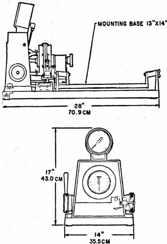
Fig. 1-1. Small-engine dynamometer.
As a general rule, torque is greatest at medium engine speeds. Friction and reciprocating losses are low and the engine has time to breathe a full charge of gasoline and air. As the speed increases, the friction load generated by the rings, piston, and bearings increases dramatically. In most cases friction goes up as the square of the rpm: for example, at 9,000 rpm, the friction will be (3 or nine times what it was at 3,000 rpm. The same is true for reciprocating loads—the energy to move the piston and the valve up and down also increases as the square of the speed. The carburetor, induction tract, and muffler also lose efficiency as the gas flow velocity increases.
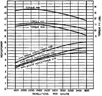
Fig. 1-2. Horsepower vs torque. The torque curves are flat showing
that these Kohler engines have good “pulling” characteristics across
the rpm range.
Larger engines, bigger parts, and more and heavier reciprocating masses take their toll. This is why model airplane engines often develop 3 hp or even 4 hp per cubic inch while a nine cubic inch Briggs and Stratton is rated at only 3 1/2 hp. The problem can be solved at least partially by going to more cylinders. The last 125 cc Honda racing motorcycle had five cylinders, each no larger than a thimble.
But while, small engines (or cylinders) can develop more horsepower per cubic inch, they are limited in torque. The larger engine will produce more torque simply because it burns more fuel and oxygen per cycle. There is no substitute for cubic inches—at least where midrange performance is concerned.
Number and Placement of Cylinders
The first decision an engine designer must make is: based on the expected usage, how many cylinders must this engine have? While most small gas engines are singles, some have as many as eight cylinders. The single-cylinder engine is mechanically simple, inexpensive to manufacture, and easy to service in the field. Good torque is also a characteristic of most singles. The piston area is larger than on an equivalent multicylinder engine, thus giving more surface for the explosion to push against.
But there are disadvantages to the single as well. There is no fail-safe capability. On a multicylinder engine, however, if a spark plug, or a piston, or a valve fails, the engine will still run. The mechanical complexity of a multi increases its reliability. And this complexity is not as expensive as it might look. Once the machine tools have been set up, it costs little more to make four to six cylinders rather than one. The multi also comes out ahead on the basis of power pulses per revolution. In extreme performance situations, the multi uses its smaller piston area to an advantage. Less area at the crown of the piston means that there will be relatively more area along the sides on the piston skirt. The skirt transfers heat from the crown to the cylinder walls. The more area in contact with the walls, the more heat will be transferred, and the less likelihood of holing a piston or scoring a cylinder wall.
Small industrial engines are classified according to the plane of the crankshaft relative to the ground. Vertical shaft engines are used on most rotary lawnmowers. The end of the crank provides a convenient mounting point for the blade. Horizontal engines have the crank parallel to the ground and are used on reel type mowers, power tools, and Go-Karts. Other than the position of the shaft and the carburetor float, these two styles of engine are similar.
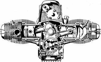
Fig. 1-3: Horizontally opposed twin BMW motorcycle engines are almost
perfectly balanced.
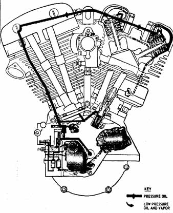
Fig. 1-4. Harley-Davidson V (vee)-twin.
Classification is also by the placement of the cylinders. A horizontal-crank single with the cylinder inclined is often called a sloper. Continental and Reo have used this pattern for their small industrial plants. The main advantage seems to be compactness. Horizontally-opposed engines are multis with the cylinders 180 degrees apart. A famous example from the automotive world of “pancake” configuration is the Volkswagen. Some Power Products two-cycles, the Kohler K482 and K662, and the current range of BMW motorcycles, are horizontally opposed (Fig. 1-3). These engines are compact, easy to cool, and have good inherent balance. The vee type is similar, except that the angle between the cylinders is smaller. Most vee’s are built with an included angle of 90 degrees between the cylinders, although a few have been as narrow as 60 degrees (Fig. 1-4). A little thought will show that the firing impulses on a twin-cylinder vee are uneven (which accounts for the loping idle of the big Harleys, but this is not noticeable at operating rpm. The vee configuration is also found on some of the large outboards. Both the horizontally opposed and the vee types use a single crank throw for two cylinders. Looking down on the engine, you’d see that the bores are offset by the width of the rod. The short, stubby crankshaft and the rectangular block resist distortion.
Another configuration which should be mentioned, if only in passing, is the square four. Pioneered by European aircraft designers, square fours came into the United States on Ariel motorcycles. These engines had four cylinders and two crankshaft s. laid side by side. The cranks were connected by a pair of gears. Good balance was achieved, since each half of the engine turned the opposite direction, but the design was complicated and expensive to maintain.
Currently, the most favored configuration for small, multicylinder power plants is the inline engine, examples of which are shown in Figs. 1-5 and 1-6. Typical examples are the Honda multis, the BSA and Triumph twins, and Johnson and Mercury outboards. Advantages are ease of manufacture, buyer acceptance (because of automobile practice. people seem to accept this configuration as “natural” L and the excellent balance afforded by threes and sixes.
Inline engines are further classified as to the position of the block in the frame. The engine may lie transversely or longitudinally. On liquid-cooled designs the lay of the engine is a matter of design convenience, but on motorcycles the transverse position has an important advantage. All the cylinders are in the air stream and are cooled equally. The Nimbus pictured in Fig. 1-5 suffers from overheating of the rearmost cylinders.
Fig. 1.5 Four-cylinder inline Nimbus motorcycle engine.
Fig. 1-6. Four-cylinder inline engine mounted transversely.
Classification of Engine by Speed
On the basis of the torque and horsepower curves, engines can be divided into high- and low-speed types.
Low-speed engines are designed to be operated in the range of 3,000 to 4,000 rpm. Usually of heavy, cast iron, construction, these workhorses drive pumps, generators, and the like. High-speed engines are “redlined” at anywhere from 7,000 to 11,000 rpm and are used where engine weight is a critical factor. Some of these engines develop better than one horsepower per pound. High-speed engines are used in power chain saws, Go-Karts, and some of the faster motorcycles. It is generally believed that high-speed engines are less durable than their low-speed counterparts. In the days of babbitt bearings and cast iron pistons, this may have been true. But today, thanks to modern design techniques (short strokes and smaller, lighter reciprocative masses), close manufacturing tolerances, and advances in metallurgy, high-speed engines are as long-lived as any.
Vibration
Piston engines generate vagrant forces that have nothing to do with turning the crankshaft. The piston, rings, wrist pin, and the upper half of the connecting rod come to a screeching halt twice each crankshaft revolution. At the upper limit of piston travel, the position known as top dead center or TDC, the piston is at the point of changing direction and is “dead” in the bore. The same thing happens at bottom dead center (BDC). Unfortunately, the piston and other reciprocating parts have weight or mass. And mass means that they resist changes in velocity and direction. If the piston assembly had its way, it would go crashing through the cylinder head or the oil pan.
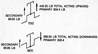
Fig. 1-7. Primary and secondary forces acting on the piston.
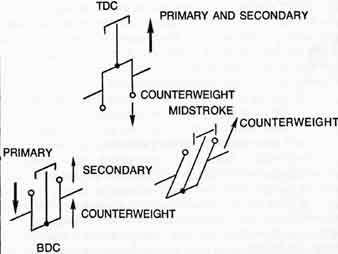
Fig. 1-8. The effects of counterweighting.
The forces generated by the reciprocating masses are known as primary shaking forces. At TDC they act to lift the engine bodily and at BDC send it crashing against its mounts. In addition, there are secondary shaking forces generated by the swing of the connecting rod. The secondaries amount to about 14 of the primary forces. At BDC the secondary force works in opposition to the primary and cuts the downward thrust of the engine by about 25 percent. At TDC the secondary acts in conjunction with the primary to lift the engine. TDC forces total 50 percent more than BDC forces.
By formula:
where
F = 0.0000142 W N2 S
F = primary shaking force
W weight of the reciprocating parts
N = rpm
S = stroke
Assume that we are dealing with a single-cylinder engine with a reciprocating weight of 0.5 lb. The stroke is 2.5” and the governored free-running speed is 4500 rpm. From the formula the primary shaking force is 359.4 lb (Fig. 1-7). The secondary—amounting to 25 percent of the primary—adds 89.95 lb for a total of 449.25 lb. The BDC force is 269.55 lb.
Fortunately, these forces do not endure long. Imagine what the situation would be if they did: A rotary lawnmower would run pell-mell over the operator as the piston came to a stop at TDC and jerk him forward at BDC.
But, however brief their duration, these forces exist. All modern engines compensate for them by adding counterweights to the crankshaft.
Figure 1-8 illustrates the effect. At TDC the rotating mass of the counterweight is directly below the piston and generates a force in opposition to the primary. And at BDC the counterweight tends to lift the engine, effectively balancing the BDC primary. The price is an unopposed transverse force generated by the counterweight at the midpoint of the stroke that tends to move the engine to the side.
Forces created by the rotating counterweight are constant and radial, while those generated by the piston and rod assembly are periodic and longitudinal.
Nobody attempts to counterweight reciprocating masses completely. If the TDC complement were 100 percent balanced, the BDC complement would be 25 percent overmatched. And the TDC force would appear 90 crankshaft degrees later as side thrust. Balance factors in practical engines are from 40 to 60 percent of the reciprocating mass. The exact factor is subject to experiment and engineering judgment. To some degree it becomes a matter of how you like your vibration—in line with the bore or at right angles to it. The arbitrariness of this procedure was demonstrated several years ago when Clinton issued a series of replacement crankshafts giving a greater balance factor for engines already in the field.
There are alternatives to simple counter-weighting. Adding cylinders almost always aids in balance. Opposed twins attain almost perfect balance if the crankpins are offset so both pistons reach the ends of travel simultaneously. At mid-stroke the counterweights are in opposition and mutually cancel. The only difficulty with this arrangement is that the engine tends to yaw on the crankshaft axis. The moment of yaw is determined by the distance between crankpins. The greater this distance is, the more pronounced is the tendency toward gyration. This phenomenon is known as a rocking couple.
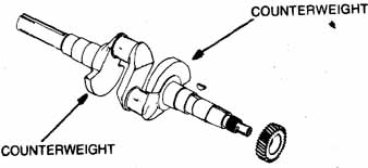
Fig. 1-9. A Kohler 180 deg crankshaft.
A 180 degree crankshaft assembly for a two-cylinder inline engine is shown in Fig. 1-9. As one piston goes down, the other goes up. Balance is less than perfect because of the rocking couple and because the secondary forces reinforce each other. If both crankpins are on the same plane, as in the English parallel-twin motorcycle configuration, the balance is the same as a single. Both pistons move together as one.
A three-cylinder engine with crankpins spaced at 120 degrees has perfect primary and secondary balance, although there is an unbalanced couple. An inline four with crankpins paired 180 degrees apart has an unbalanced secondary equal to the primary generated by one piston. Of all small engine configurations, the inline six is the smoothest. It is equivalent to a pair of threes, but without the rocking couple.
The designer may not have the freedom (because of cost, space. or market considerations) to add more cylinders. There are ways of civilizing a single. Briggs and Stratton uses an oscillating balance in some engines Fig. 1-10 . Paired weights flank the connecting rod and ride on crankshaft eccentrics. The link secures the weights to an anchor pin on the side of the block. As the engine runs the weights oscillate two and fro. Since the low point of the eccentric is next to the crankpin, the weights move down as the piston reaches TDC and move up at BDC. Primary forces are cancelled as well as they can be.
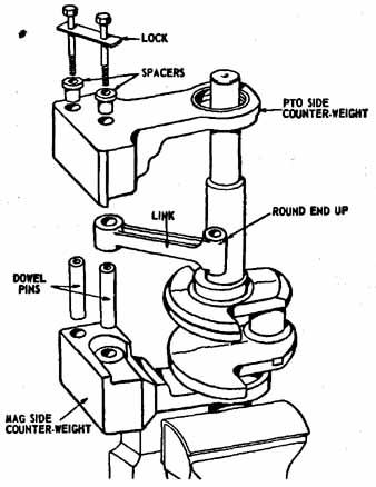
Fig. 1-10. Oscillating counterweights are available for some Briggs
and Stratton engines.
McCulloch has taken another tack in the BP series prototypes. These prototypes have a secondary or balance piston working in conjunction with the primary piston. The primary piston generates the power while the balance piston compensates for shaking forces. In addition the balance piston pumps the air/fuel mixture into the crankcase. It is not a supercharger and does not boost power, but it does make these engines more tractable. Unlike most high-performance two-cycles, BP prototypes are tolerant of restrictions in the intake and exhaust plumbing and are simple to tune.
Some Briggs, Kohler, and Tecumseh singles are tamed with contra-rotating weights. The weights help compensate for primary forces (Fig. 1-11A and B) while balancing the crankshaft counterweight at mid-stroke (1-11C). In all, this is a very elegant solution to a vexing problem.
Torsional vibration—the tendency of the crankshaft to wind and unwind—is another matter. During the power stroke the crankshaft tends to wind like a great spring because of the force exerted on it by the connecting rod. A few hundredths of a second later the crankshaft relaxes. The amount of twist is trifling, but it is enough to be felt as vibration.
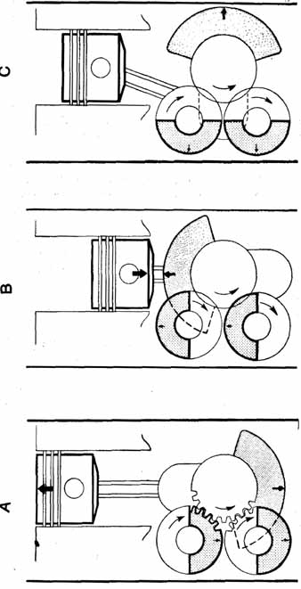
Fig. 1-11 Rotating counterweights used on some single-cylinder engines.
Like a tuning fork, every crankshaft has a natural frequency of vibration. If the impulses from the connecting rod correspond to this natural frequency, the crankshaft twists more with each impulse. A few minutes of this—or even a few seconds—can be enough to snap the crankshaft.
Engineers design the crankshaft so that its natural frequency is well beyond the speed range of the engine. Unfortunately there are sub-harmonics that occur at fractions of the fundamental frequency. It is therefore impossible to design an engine that is smooth all the way across the rpm band. At one speed or another, the crankshaft flexes and produces vibration.
Noise
Wherever there is high-frequency vibration, there is noise. A few years ago, hardly anyone was concerned with the noise made by small engines, and if you couldn’t nap because your neighbor was mowing his lawn, you cussed and put a pillow over your ears. But things are different today. The proliferation of small engines into all corners of the environment—the lakes, the desert wilderness, the winter forests, and into the heart of the cities—has aroused national attention on the noise problem. Chicago already has a noise ordinance on the books which, if enforced, would effectively ban small engines from the city. The Federal Government is expected to follow suit.
Why is it that one power chain saw makes more noise than fifty automobiles? The answer is complicated. It is not that small engine manufacturers want to damage the hearing of their customers (studies have shown that hearing loss, especially for high frequencies, has occurred among chain saw operators and motorcycle racers), or invoke the wrath of the government. Small engines have a high specific output when compared to automobile engines. The little engines work harder and so are inherently noisier.
The problem is compounded by the fact that single- and twin-cylinder mufflers are not as efficient as those designed for multi-cylinder units. In any exhaust system, there are alternating high- and low-pressure waves. When the exhaust valve or port opens, it releases a high-pressure wave which carries a near vacuum in its trail. Automobile engineers have learned to combine these low- and high-pressure waves to give a low average pressure. Consequently, the level of sound is reduced. In theory this could be done with singles and twins, but the plumbing would be as large as the engine. Instead, small engine designers have to be content with baffles (which slow down the exhaust gases and reduce their sound-making potential) and packing, which absorbs some of the high-frequency sounds.
But even with a dead silent muffler, small engines are still noisy. Recently Tecumseh ran a series of tests on a 3 1/2 hp four-cycle lawnmower. The results are interesting. At 3.225 rpm the engine produced a sound level of 68 dB A. The term dB A refers to decibels measured at fifty feet (the “spectator distance” for most power equipment) and sound consisting of frequencies which are intrusive on human hearing. With the exhaust completely muffled, the engine still produced 65.3 dB A. Since the decibel scale is logarithmic, small changes are significant—most people can perceive a sound variation of 1 decibel—but this test showed that the muffler is only a small part of the problem. Other tests have shown that larger engines are even less responsive to increases in muffler efficiency.
Much of the noise is generated in the induction tract. Air whistles through the filter and carburetor and. on two-cycle engines, the reed valve makes a distinct sound as it slams shut with each revolution of the crank. Modern engines now have more ‘hiss felt” lining the intake tract. This material absorbs sound above 2.000 Hz. (Hz = Hertz = cycles per second.) Another approach is to use fiber reeds in valves rather than the spring-steel type.
Quiet mufflers and quiet intake tracts help, and they can be achieved in the present state of the art. Another, knottier problem, is the noise made by mechanical parts. The cylinder head vibrates with each explosion. On an air-cooled engine, the amount of sound transmitted in this way goes up as the cube of the bore diameter. For example, triple the size of the cylinders and the noise factor goes up nine times. Another culprit is the operating clearances on reciprocating parts. Noises caused by piston slap (the side to side movement of the piston in the bore), valve lash, and the clearances between the crankpin and the connecting-rod bearing, all reinforce each other. Timing gears are also noise makers. The flywheel and crankshaft pulley pick up vibrations from the crankshaft and radiate them outward in the manner of a “tin can telephone” such as children play with. Any large sheet metal surface such as the oil sump or the cooling shrouds also has this effect. On riding lawnmowers, it is not unusual for the whole frame to serve as a sounding box.
But progress is being made. The 1972 Mercury 650 is one of the quietest outboards ever built. It is the result of years of research in an anechoic chamber (this is a soundproof room with the inner surfaces arranged so that there will be no echoes).
Mercury engineers attacked all three areas: the exhaust, the intake, and mechanical noise. A new intake system was designed and the exhaust was modified to reduce the organ pipe effect. Mechanical clearances were tightened and the power head was encapsulated in a soundproof cover. As a result, the dB A level was cut in half.
Cooling
This section on cooling and the section on lubrication that follows are related because oil is also a coolant.
The best gasoline engines are only about 30 percent efficient. Only a third of the heat released by the fuel is used to make motion. The rest is wasted in friction, transferred to the pistons and cylinder walls, and expelled through the tail pipe. The temperatures involved here are high: combustion takes place at about 4.000 degrees F. The exhaust gases range between 1.000 and 1.200 degrees F. and the crown of the piston often reaches 1.000 degrees F. Without some method of taking heat out of the engine and bearings, these parts and then the engine itself would melt. At only 350 degrees F, white-metal bearings consisting of tin and lead) begin to soften.
Liquid-cooled engines use water as the medium of heat transfer. The water circulates in a double-walled chamber, called a jacket, which surrounds the combustion chamber and the cylinder bores. The water jacket transfers heat from these hot spots to the atmosphere. Most liquid-cooled engines use a radiator which is equipped with an engine-driven fan and may have an expansion tank to prevent fluid loss. Outboards and some inboard marine engines dispense with the radiator since they draw upon an unlimited supply of cool water.
Much research has been done on the effects of different coolant temperatures. At one time it was believed that moderate outlet temperatures were desirable since the formation of scale is retarded at below 180 degrees F. Scale is a rock-like combination of minerals from the water and rust or aluminum oxide. It builds up in the water passages until, in extreme cases, the water supply is cut off entirely. And even minute amounts of scale act as insulation.
However, contemporary theory favors much higher outlet temperatures, on the order of 220 degrees F. At these temperatures, there is less of a tendency for the crankcase oil and the exhaust gases to combine and form acids. Consequently, bearing and bore life are increased. And higher temperatures mean that the oil flows easier, thus reducing the amount of energy wasted in friction. Another plus is that because of the greater differential between the water and air temperatures, a smaller radiator and fan assembly can be used. But scale remains a problem and these engines must be periodically inspected.
Marine engines with open systems, such as outboards, can require considerable water-jacket maintenance. In fresh water, mud and marine growth can block the passageways. In salt water, the problem is compounded since salt attacks cast iron and aluminum. The engine does not have to be running for the damage to occur. Dealers tell of engines rusting out on the showroom floor. Whenever an engine of this type has been operated in salt water, it must be flushed with clear, fresh water. And in no case should the outlet temperature be more than 160 degrees F. Otherwise salt will drop out of solution and cake in the jacket.
On closed (fresh-water) systems, it is advantageous to use 50-50 or even a 70-30 mix of ethylene glycol and water. This increases the boiling temperature of the coolant and, of course, lowers the freezing point. Ethylene glycol antifreezes sold by the major suppliers, such as Union Carbide and DuPont, also contain rust inhibitors and water-pump lubricants.
Most liquid-cooled engines use a pump to circulate the water, although a few still employ the thermo-siphon method which Henry Ford chose for his Model T. Cold water is denser than hot water circulation will result if the water is heated at one point and cooled at another. Thermo-siphon systems use a hot water line that runs from the cylinder head to the top of the radiator. Needless to say, circulation is rather leisurely, and this method is not used on high-performance engines.
Air-cooled engines dump their heat directly into the atmosphere without the intermediary of a liquid coolant. These engines depend upon rows of fins cast into the cylinder head. Barrel, and (optionally) into the sump or crankcase. Heat generated by combustion and friction passes through the engine metal where it goes to the fin roots and out the sides and tips. Two principles are involved: convection and radiation. The former is much more significant and refers to the removal of heat by a draft of air over the fins in a manner similar to the action of water moving through the jacket. Although air is approximately 3500 times less effective than water in its ability to absorb heat by convection, it is adequate for less-than-ultimate performance engines. When power outputs climb to 350 hp/liter, water-cooling begins to look more and more attractive.
In motorcycle and “free air” snowmobile engines, convection currents are generated by the forward movement of the vehicle. When the machine is stationary, cooling depends upon radiation. Small convection currents may be generated between adjacent fins, but these currents are too weak to be of much use. Radiation is the transfer of heat from a warmer to a cooler surface without heating the intervening air. It is the same phenomenon that accounts for the warming of the earth by the sun. In an air-cooled engine, radiation losses rarely account for more than ‘/8 of the total heat output, although this figure can be increased in cold weather and by painting the head and barrel flat black.
Stationary engines and those that are buried under a cowling (like those used to power all-terrain vehicles and most snowmobiles) use some form of forced-draft cooling. Air is circulated over the engine by means of a fan and shroud work.
Radial-fan cooling is the cheapest and most popular approach since it uses the flywheel as the fan (Fig 1-12). Other than the shrouding, no extra hardware is needed. Air enters at the flywheel hub and is flung outward by vanes cast on the rim of the wheel. From there it is collected by a sheet metal shroud and guided over the engine by additional shrouds.
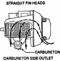
Fig. 1-12. Radial fan operation. Carburetor Side Outlet; Straight
Fin Heads.
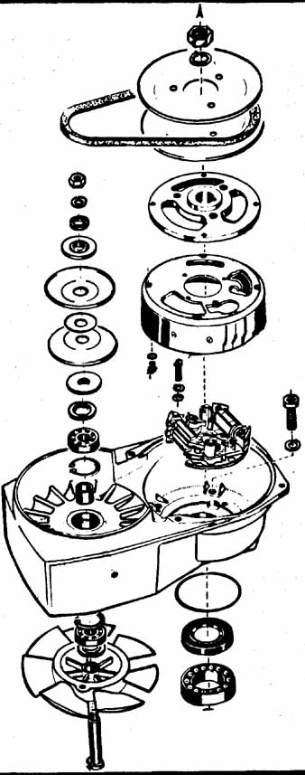
Fig. 1-13. Axial fan exploded view.
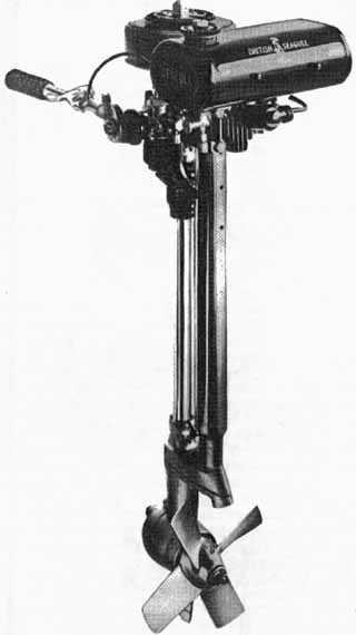
Fig. 1-14. British Seagull outboards have air-cooled heads and water
cooled barrels.
Axial-fan cooling is a more sophisticated proposition. The fan is a separate entity, mounted on a shaft above the flywheel and driven by a V-belt. The airstream moves in a straight line through, or axially with the fan. Figure 1-13 illustrates a typical example. While this arrangement adds to the cost of the engine and depends upon a vulnerable drive belt, it improves engine performance. Axial fans are more efficient than radial types (particularly if the radial fan is a disguised flywheel) and the designer can use a stator plate to increase efficiency even more. (The stator plate is the finned casting to the right of the fan in the illustration.) How much more efficient axial fans are is a matter of dispute. However, it is known that the typical forced-draft system absorbs a great deal of power. At 5000 rpm a 20 hp engine expends more than 10 percent of its power in cooling.
All axial fans and nearly all radial fans exhaust over the engine. Suction fans are a rarity, but are found on a few stationary engines and on some European generator sets. These generators are driven directly from the crankshaft and are cooled by the engine fan. A blower fan would deliver air that had been heated by contact with the engine; a suction fan at least insures that the generator is bathed in a current of cool air. On the debit side, fan efficiency is down since the blades tend to slip in warm air.
Finned engines are popular because they are cheap and portable. Nearly all of the 45 million small utility engines used in this country are air cooled. The principle has even been applied to outboard motors, motors which operate on natural radiators. Clinton and Tecumseh make a line of small, air-cooled power-heads, and British Seagull combines both principles. Seagull motors have water-cooled jackets and air-cooled heads (Fig. 1-14).
Lubrication
Two-cycles are lubricated by oil mixed with fuel. Relatively small amounts of oil are required—some engines can run as lean as 100 parts of gasoline to one part of oil. Until recently, all two-cycles required that the owner mix the oil with the fuel in the correct proportions. The drill was messy and wasteful. Some owners felt that if a little oil was good, more would be better. And lubrication requirements vary with rpm and load; the 100 to 1 figure quoted previously is specified for full-throttle operation. At idle, these engines have more oil than they need. The excess accumulates in the exhaust ports as carbon or is expelled into the atmosphere. Japanese engineers made a considerable breakthrough with the auto-lube system (Fig. 1-15). Essentially the auto-lube is a variable displacement pump controlled by the position of the throttle. Oil is delivered as the engine needs it in proportions which vary from 400 to 1 at idle to 30 to 1 on acceleration. If the government moves to control air pollution created by small engines (motorcycle manufacturers must reduce emissions by 75 percent in 1978), some form of auto-lube will be mandatory on all two-cycles.
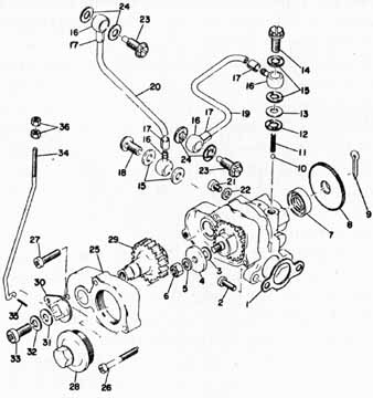
Fig. 1-15. Oil injection pump used on Yamaha snowmobiles.
Four-cycle lubrication systems are divided into two broad classifications. The simplest is the splash system. Oil in the crankcase is splashed around the moving parts as the crankshaft throws come down. Sometimes there will be a “scooper on the end of the connecting rod or (on Briggs and Stratton designs) a vaned wheel which revolves with the crank. The splash system is adequate for low-speed engines, but has serious drawbacks when the rpm goes up. In the first place, the engine must be an L-head; overhead valve gear is far too remote to receive oil. At high rpm, bearing lubrication is a problem. And there is the power loss caused by “windage, “ the friction of oil against the throws.
A better system is to employ an oil pump. Most oil pumps are the geared type. On most engines, the pump consists of two meshed gears turning in a closed housing. Oil is picked up on one side and is forced out the other. Small Tecumseh engines are somewhat unusual since they employ a reciprocating pump and check valve arrangement. In either case there is a spring-loaded relief valve to keep the pressure from exceeding preset limits.
Refer again to Fig. 1-4 which shows the oil circuits of a typical Harley-Davidson engine. Note that every friction surface receives oil, either under pressure or by gravity on the return to the crankcase. The Harley uses a dry sump, that is, the crankcase is dry and oil is stored in an external tank. The oil pump is really two pumps in one; one side pressurizes the engine and the other side evacuates the crankcase. The pump which discharges the crankcase has a greater capacity than the pressure pump; this keeps the case from flooding. Dry-sump lubrication has certain advantages for high- performance applications. Since the crankcase is dry, there can be no power loss due to windage. The external tank, mounted well away from the engine block, tends to act also as an oil cooler. And a dry-sump engine can be made with a low center of gravity, which aids handling. The penalty is additional complexity and, on most designs, external oil lines which are subject to leakage.
A number of Kohler vertical crankshaft engines employ a dry-sump system with an integral tank. Since the tank and crankcase are part of the same casting, there are no external oil lines to foul.
The most unusual feature of the Kohler system is the absence of a proper oil pump. The piston is the pump element, and works in conjunction with the sealed crankcase and check valve to deliver oil to the upper main bearing.
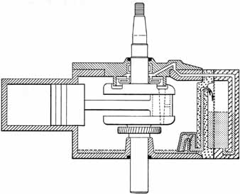
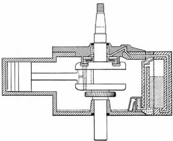
Fig. 1-16. Lubrication for Kohler KV141 engines. In view A the piston
is at BDC, the crankcase and oil sump are under the same pressure.
In view B the piston is at TDC, the crankcase is under partial vacuum
while the sump is still pressurized.
Figure 1-16 illustrates the operation. In view A, the piston is at bottom dead center and has displaced part of the crankcase volume. Because the crankcase is sealed, it comes under several pounds of pressure. Oil collected at the bottom of the case from previous cycles is forced through the check valve and to the sump. In view B, the piston has returned to top dead center and leaves a trail of vacuum in its wake. The check valve closes, isolating the sump from the crankcase. Oil, in response to the low pressure in the case and the high pressure in the sump, flows through the gallery and spills over the thrust bearing.
The thrust bearing, shown more clearly in Fig. 1-17, flings the oil outward where it collects in a deep channel on the upper crankshaft web. This channel is open to the crankpin and is deep enough to serve as an oil reservoir should the system momentarily fail. Oil passes through the hollow crankpin and some of the flow is diverted to the big end bearing. The remainder dribbles down into the sump.
The baffle behind the sump check valve insures oil delivery at extreme angles (up to 45 degrees) of engine tilt.
The system will continue to function with only a few ounces of oil in the sump, although one can expect bearing damage from overheating. These KV141 engines are designed to hold one quart of oil.
Smaller KV1O1 and KV121 engines use the crankcase as the reservoir. The camshaft is rifle drilled and cross drilled at the bearing ends. The case comes under pressure when the piston is at BDC. At the same time the lower camshaft port is open to the sump, and an emulsion of air and oil passes into the hollow camshaft. At TDC the camshaft has turned so its upper cross-drilled port is aligned with the upper main bearing. Since the oil charge inside the cam is still under pressure (because of the air bubbles in it), oil flows out of the cam and into the main bearing. From there it collects in a cavity in the upper crankshaft web and proceeds through the crankpin and to the big end bearing. The arrangement is similar to the one illustrated in Figs. 1-15 and 1-16. Oil capacity is 1 pt.
Motor oil has four main functions. The first is to reduce friction by interposing a film between rubbing parts. This film may only be a few thousandths of an inch thick, but as long as it remains intact it will prevent wear and heat buildup. Most of the wear on the typical engine occurs on cold starting. The oil has drained off the parts, and for the first few revolutions, there is no lubrication to speak of. When rebuilding an engine, mechanics use liberal quantities of oil on all friction surfaces. On four-cycles, some even go so far as to pressurize the oil galleries before the engine is started for the first time.
Another function of oil is to act as a seal between the piston and the bore, and between the valves and their guides. The sealing effect is considerable, especially when the engine is worn. A major reason why engines which have been inoperative for a long period are difficult to start is that the oil has drained from the cylinder bore.
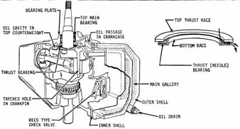
Fig 1-17 Oil is distributed by centrifugal force and gravity.
A third function is to remove heat. In this sense, all engines are liquid-cooled. The figure is considerably less for a two-cycle engine, but on a typical four-cycle, some 40 percent of the cooling chore is handled by the oil. This is why the crankcase oil level is so critical. Engines which run low on oil fail, not because of lack of lubrication—there is usually enough for that—but because of heat build up. Small quantities of oil cannot dissipate the heat quickly enough. Some four-cycles employ an oil radiator to help keep temperatures below the critical 250 degrees F for 30W oil and 300 degrees F for SOW.
Finally, oil must resist and neutralize the harmful by products of combustion. A gallon of gasoline passing through the combustion chamber will combine with oxygen to release approximately one gallon of water, up to (depending on the engine) 0.1 gallon of unburned gasoline, and traces of hydrochloric, hydrobromic, and various nitrogen- and sulfur-based acids. There will also be small quantities of varnishes, resins, soot, and lead salts. Most of these chemicals are expended out the tail pipe, but some of them get past the rings and are trapped in the crankcase. One study has shown that most bore wear is not caused by friction, as one would suppose, but is caused by acid etching. Sludge accumulates around the piston rings and causes sticking. In extreme cases, sludge can block off oil passages and fill the screens on oil pumps. Water causes rust, and the unburned fuel dilutes the oil, increasing the wear factor.
In order to take some of the load off the oil and to extend oil change periods, more and more small engines are employing some form of oil filter. The filter element, which is usually pleated paper (although other organic materials such as cotton stuffing have been used), is designed to trap solids. Modern filters can trap particles as small as 25 microns in diameter (a micron is 0.00039”). A good filter will reduce wear and will localize damage if one part begins to pulverize. Fortunately, most small engine filters are in series with the pump—all oil going to the engine must pass through the filter. As a safety factor, if the filter is stopped up, a pressure relief valve will open, insuring full lubrication as the oil bypasses the filter. A few of the older engines, used mostly on construction work and in marine applications, had bypass filters. These filters were in parallel to the main oil line. Sooner or later all the oil would be filtered, but in the meantime loose particles were free to circulate around the engine.
Regardless of advertising claims, no filter can remove liquid contaminates. To do so, the filter would have to be a miniature oil refinery.
All motor oils are rated by viscosity, which is defined as the resistance of a fluid to the force that causes it to flow. The higher the number, the thicker, or more viscous, the oil. Thus SAE (Society of Automotive Engineers) 40 has more resistance to flow than does SAE 5W. The W suffix means that the oil has been tested for winter operation. The industry has had to provide different weights because oil tends to lose its viscosity as the temperature goes up. A 5W oil is excellent for sub-zero operation, but would thin to uselessness in the Mojave Desert. In the last decade, multigrade oils have been developed—such as 1OW-40-—which hold their viscosity over a wide range of temperatures.
In addition to viscosity, motor oils are classified by the American Petroleum Institute for load strength, acid neutralization, resistance to sludge buildup, and rust inhibition. Because of ever-extended oil change intervals for new American cars, the rating system is in a state of flux. The rating system is based on automotive use but is applicable to small engines. Hence, do not use less than API Service MS (Severe Service under the old system) in any engine. Under the new rating, devised for 1971 cars, use no lower quality than API SE. the best oil available at this writing.
Oils are also classified as detergent and non-detergent. Detergent oils contain dispersants which keep sludge and carbon particles in suspension. All manufacturers recommend the use of detergent oils—in fact, with multi-grades there is no choice in the matter. The only caution is that when used in an old, dirty engine, a detergent oil can loosen the accumulated sludge to the point where oil passages may be blocked.
Switching to different brands of oil is frowned on by many mechanics, but there is no evidence that the practice is harmful. The military has been doing it for years. However, it is wise to stay with the major refiners; there is no policing of API classification numbers, and some of the “cheapie” oils are not what they are claimed to be. Oil additives should be avoided. Some, especially those that contain metals, are positively harmful. Others, while they can improve poor grades of oil, are more expensive than good oil to start with.
While all small engine makers suggest a major brand name and that API MS quality or better be used in their products, there is some difference of opinion on the grade. For the Kohler twin cylinder industrial four-cycles, the specifications are as follows:
TEMP. below 0 degrees F. 0 to 30 degrees F. above 30 degrees F. |
OIL GRADE 5W-20 10W-30 40 |
Other manufacturers of air-cooled engines show the same reluctance to use multigrade oils in the summer. BMW suggests 10W-50 below 86 degrees F, and SAE 40 above that temperature or for substained high-speed operation. Two-cycles operate best on the specially formulated oils available from the major refineries or from the factory. In the case of ultrahigh output engines, it is wise to follow the manufacturer’s instructions as to the particular brand of oil.
Fuel
We think of gasoline as the fuel, but actually it only makes up a small part of the mixture. For every gallon of gasoline burned in the engine, the oxygen from 9,000 cubic feet of air is also burned. Normally, the air requirement is taken for granted, since most small engines operate where they have sufficient air supply. Probably the only exceptions are inboard marine engines and engines operated below decks on large vessels.
Gasoline that is produced from natural gas is called casing-gas, but most gasoline is processed from petroleum. To convert crude oil to gasoline, the liquid is heated in tall fractionator towers until the lighter compounds vaporize. These components are then cooled down to the liquid state and further processed. Primarily gasoline consists of carbon and hydrogen atoms and various additives to increase the octane number, retard varnish formation, and to improve cold starting. The larger refineries match their product to seasonal changes.
The most important breakthrough in gasoline technology was made half a century ago by Charles F. Kettering. He discovered that trace amounts of liquid (tetraethyl) lead would significantly improve the antiknock characteristics of gasoline. Previous to this discovery, gasoline engines were limited to compression ratios of three or four to one. Almost immediately, ratios went up to six or seven to one, and today many engines have ratios of eleven or more.
Without tetraethyl lead or an equivalent additive, gasoline has a tendency to detonate under compression. Detonation is a wild, uncontrolled explosion which occurs before the piston is at top dead center. Tremendous loads are imposed on the bearings and, on some engines, the operator can hear the distinct ping. In order to get some sort of standardization, the industry has agreed upon an octane number. The higher the number, the more “ping resistant” the fuel. In the United States, regular gas averages 94 octane and premium varies between 97 and 100 by the research method. Another way of calculating the octane number is the engine method which more nearly reflects commercial requirements. Engine octane is about ten points lower than research or passenger car octane numbers. The octane number on American service station pumps is the average of research and engine numbers.
As long as an engine does not ping or knock (this will usually occur under load at part throttle) there is no reason to use higher octane fuel. At low rpm carbon builds up in the chamber and on the top of the piston, increasing the compression ratio, and thus an engine might require higher octane as it ages. But this is unusual in small engines, which work hard and keep themselves fairly clean. High test will not give better economy than regular grades of fuel. Most commercial gasolines have about the same latent heat per pound. Nor is it necessary to run an occasional tank of high test through the engine to “clean” it.
Fuels with carburetor cleaners should not be used in two-cycles because these cleaners have a tendency to wash the oil off the parts.
Currently there is controversy about lead in gasoline. From a serviceman’s point of view, low lead or no lead fuels are advantageous. With these fuels, there seems to be less spark plug fouling on two-cycles and there is definitely less oil contamination in four-cycles.
OPERATING PRINCIPLES
Conventional engines are classified as two- or four-cycle. Each upward or downward stroke of the piston is called a cycle: the two-cycle fires once every revolution of the crankshaft or every two cycles), and the four-cycle fires every second revolution. As could be expected, each type has certain advantages. The two-cycle is mechanically simple; and in the smaller displacement classes, the two-cycle can generally be counted upon to outperform the equivalent four-cycle. But the cost of this performance is increased fuel consumption, poor part-throttle operation (although this problem is being surmounted), and, at least in some cases, excessive intake and exhaust noise. The two-cycle is favored in light-weight recreational equipment and in portable power tools. The four-cycle, on the other hand, suffers a built-in weight and cost penalty, which is compensated for by tractability, good fuel and oil economy, and ease of repair. At this writing, the four-cycle produces less air pollution than the two-cycle “smog motors.” Some of the Japanese manufacturers promise a solution to this problem, apparently by the use of forced air injection at the exhaust port.
Four-Cycle Operation
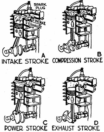
Fig. 1-18. Four-cycle operation.
See Fig. 1-18. As the piston moves down on the intake stroke, the intake valve opens. Fuel and air enter the cylinder. The valve closes as the piston moves up, past BDC, and compresses the mixture on the compression stroke. Near TDC, ignition occurs and the piston is driven down on the power stroke. The piston moves up on the exhaust stroke, expelling the burnt gases into the atmosphere through the open exhaust valve. At this point, the four cycles are complete and the process begins again with the intake stroke. The energy required to move the piston and work the valve gear is stored in the flywheel between power strokes.
The valves on a four-cycle operate from a camshaft which is driven at half engine speed. The cam is fitted with pear-shaped eccentrics, called lobes; tappets press against each lobe. The lobe-tappet arrangement converts rotary to reciprocating motion, which opens and closes the valves.
When the valves are positioned alongside the piston, the engine is known as a flat or L-head, as in Fig. 1-18. This configuration is mechanically simple and, consequently, inexpensive to manufacture. However, the flat-head design is not really suitable for high compression ratios. These L-head engines are limited to applications such as lawnmowers and auxiliary power supplies. A variation of the side valve design is the T-head, which has a separate cam for the intake and exhaust valves. From a mechanic’s point of view, this design is significant because both cams must be timed.
Overhead valve or I-head engines have the valves positioned in the head, directly over the piston as in Fig. 1-19. Such a configuration allows a compact combustion chamber and consequent high compression ratio. But this advantage is bought at the cost of additional parts; in order to transmit reciprocal motion from the tappets to the valves, the OHV design requires pushrods and bell cranks, called rocker arms. These extra parts add considerable inertia to the valve gear. While insignificant from the point of view of the power required to drive it, at high rpm the added inertia is a serious handicap. The combined weight of the tappets, pushrods, valves, and part of the rocker arms, overcomes the tension of the return springs and the valves stay open. The engine coasts, without compression, until the rpm drops enough for the springs to take hold. This phenomenon is known as valve float.
Overhead-valve designs are found on a wide range of industrial engines (especially those which have come on the market through military surplus), and on a large number of motorcycles.
Gradually, however, OHV types are being replaced by overhead cams. The cam—or pair of cams—is positioned in the head, above the valves. Single overhead cams (OHC) employ fingers, working off the lobes of the cam, to open the valves. Since most of the reciprocating weight of the valve train is done away with, high rpm operation is possible. Double OHC designs go one step further and eliminate the weight of the fingers: one cam works directly on the intake valves and the other on the exhaust.
A disadvantage of the OHC is that the remote position of the cam calls for some fairly elaborate drive mechanism. The problem is not made any simpler by the fact that the cam has an uneven load. As the lobe revolves, it pushes against the resistance of the valve spring until the valve is fully opened. As the valve closes, the spring attempts to push the cam in the direction of rotation. At the heel of the lobe, there is no pressure against the valve, and the cam turns freely. In the past, a few English and Continental motorcycles have used a shaft and pinion gear arrangement to drive the camshaft.
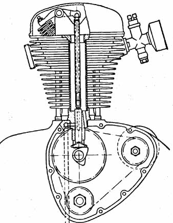
Fig. 1-19. A typical overhead-valve motorcycle engine.
Pure gear drives are out of the question, except on racing machines where cost is no object. The Ford double overhead cam Indianapolis engine used a total of twenty-eight gears between the crank and camshaft! Today almost all manufacturers use chain drive. Single- or double-row chains are found on Hondas, Triumphs, and Yamahas. Chains are quiet and cheap, but they do tend to stretch in operation, and a well-engineered design includes some sort of chain tensioner. Another approach is to drive the cam with a toothed fiberglass belt. While these belts have been highly successful in Fiat, Pontiac Tempest, and Vega engines, they have not yet filtered down to small engines.
Two-Cycle Operation
The key to understanding the operation of these engines is to remember that the piston acts as a valve and as a pump. As the piston moves up and down in the bore (Fig. 1-20), it uncovers ports which allow the fuel charge to enter and the exhaust gases to escape. At the same time, the underside of the piston functions as a kind of pump.
When the piston moves up in the bore on the compression stroke, it leaves a low pressure area behind it. Fuel and air move into the crankcase to fill this partial vacuum. On the power stroke, the piston moves down in the bore, pressurizing the crankcase, and forcing the fuel charge into the bore by means of a transfer port which empties into the bore. Of course, the crankcase is airtight and there must be some method of preventing reverse flow through the carburetor. American designs, such as West Bend and Power Products, often employ a shutter or reed valve between the crankcase and the carburetor (inset, Fig. 1-20). When there is low pressure in the case, the spring steel reeds open and fuel passes through the valve. Under compression, the reeds close against their backing plates, trapping the mixture in the case where it will be pumped through the transfer port.
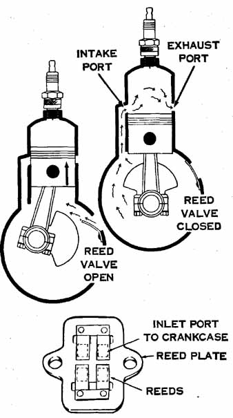
Fig. 1-20. Two-cycle engine with a reed, or leaf, valve.
Kawasaki, Bridgestone, and a few other makes use a fiber disc rather than reed valves. The disc has a cutaway on the rim, and is timed to piston motion (Fig. 1-21). A variation of the disc valve principle is found on model airplane engines; the crankshaft has a passage milled along its length and opening to the crankcase. At the moment of maximum crankcase vacuum, the passage opens to the carburetor, and fuel flows. Some engines are entirely piston controlled (Fig. 1-22).
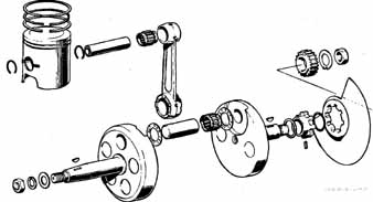
Fig. 1-21 Disc valve.
So far we have discussed events below the piston. But that is only half of the story. As the piston moves down the bore, it uncovers one or more exhaust ports. Exhaust gases, which are at greater than atmospheric pressure, escape out of the port as soon as it is uncovered. However, a more positive method is needed to insure complete evacuation, that is, scavenging. The fuel charge, entering the chamber through the transfer port, is used to force the exhaust residues out through the tail pipe. Of course, some of the fuel will mix with the exhaust and be lost. The older designs depended upon the shape of the piston crown to deflect the incoming charge away from the exhaust. A deflector piston is pictured in Fig. 1-23. While adequate for some applications, deflector pistons are heavy and prone to overheating. Newer designs employ light-weight, flat-topped pistons. The charge is introduced through multiple ports which are angled to give the mixture a swirl. In all of this discussion, it should be remembered that the gas/air vapor induction speeds are high—in the range of 900 feet per second. A deflector or a slight angle on the ports will have tremendous effect.
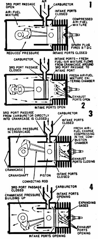
Fig. 1-22. Two-cycle engine with a piston-controlled third port.
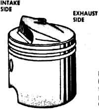
Fig. 1-23. Deflector piston installation.
Prev: (none)
Next: Troubleshooting