At the engineering firm where I work, the past few years have brought us about two dozen jobs retrofitting designs for relatively new buildings that were structurally deficient or failing for one reason or another. Typical was the work we did on a poorly designed office building. Improperly placed rebar substantially reduced the strength of a critical grade beam. After a good deal of excavation, we epoxied dowels into the old grade beam and reinforced it with 15 yd. of new concrete.
Now I notice structural problems every where I look. I can’t even go to the super market without wincing ever so slightly at the shrinkage cracks in its concrete-block walls (see image). Although these problems are how I make a living, many of them could have been avoided.
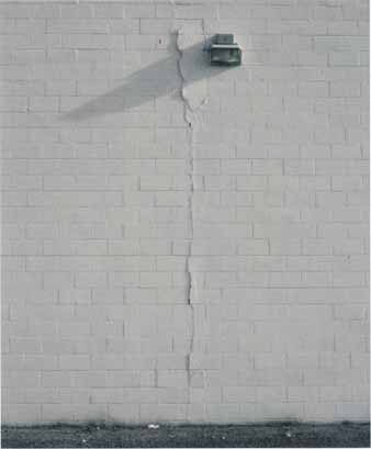 This wall made its own contraction joint. Quarter-inch contraction
joints made of a high-grade elastomeric sealant allow a block wall to shrink
as water dissipates from the grout, instead of cracking. This wall should
have had these control joints every 15 ft. to 20 ft.
This wall made its own contraction joint. Quarter-inch contraction
joints made of a high-grade elastomeric sealant allow a block wall to shrink
as water dissipates from the grout, instead of cracking. This wall should
have had these control joints every 15 ft. to 20 ft.
Concrete Strength Relies on the Right Mix and Reinforcement
Reinforced concrete is barely a hundred years old, and engineers are still refining their assumptions of its properties. Yet some contractors (even large governmental agencies) have not changed their methods in the past 30 to 40 years.
Concrete alone lacks appreciable tensile strength. Steel reinforcing, or rebar, used in concrete can't withstand compressive force by itself. Combining the strengths of concrete and steel produces the required structural properties.
Anyone who works with concrete knows that steel reinforcement provides tensile strength. But even experienced builders and designers commonly overlook an obvious consequence of this fact. Rebar must extend into concrete deep enough to develop that tensile strength. Instead of pulling out of the concrete, the bars will start to stretch.
Problems commonly arise at points where rebar changes direction and at inter sections. Take, for example, a corner in a footing that has two horizontal rebars. Workers often place the outer bar wrapping around the outside of the corner, which is correct. But then they wrap the inside bar around the inside of the corner, losing a few essential inches of development length. In side bars at corners should cross, run past each other, and extend toward the far side of the footing (see ill. below).
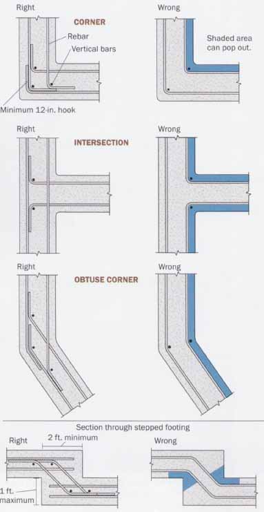
Rebar Must Be Detailed Carefully at Corners: At
intersections and corners of concrete footings and walls, problems can arise
if reinforcement is improperly placed. Steel bars must overlap the correct
length and should hook around perpendicular reinforcing. At corners, inside
bars should cross, run past each other, and extend toward the far side of
the footing. Otherwise, the inside bar in the corner lacks sufficient embedment, and the concrete then may pop out. The three pairs of drawings below are
plan views of footings. CORNER: Minimum 12-in, hook;
Rebar Has to Go Deep Enough to Do the Job
Straight reinforcing bars can develop sufficient bond if they extend far enough into the concrete. When you don’t have thick enough concrete (such as at a wall corner or at a T-intersection), a hook at the bar’s end may substitute for the lack of available embedment. If a perpendicular bar is placed inside the hook, it spreads the force to a greater area of concrete. (Usually there is a whole row of hooked bars, and a single bar can run through all of the hooks.) We like to see a bar inside the bend at any change in bar direction.
Sometimes the tail of a hook may not fit where it’s shown on the plans. Usually you can rotate the tail of the hook to clear obstacles. As long as the hook extends into concrete to develop sufficient anchorage, it’s doing its job. You should check with the designer first, though. Sometimes hook tails need to lap with other bars.
Less Water Means Less Shrinkage and More Strength
Nuisance cracking in concrete has two major causes: shrinkage during the curing process and thermal expansion or contraction due to temperature swings. Generally, shrinkage is caused as the water in the concrete gradually dissipates. As much as one- third of the water, or 5% of the total volume of the concrete, can dissipate.
The strongest concrete uses only enough water to hydrate all of the cement in the mix. Excess water leaves space in the concrete when it evaporates, making the concrete less dense and therefore weaker. (Lost water affects the concrete’s structure on a molecular level, unlike the tiny bubbles that are left in air-entrained concrete.) But strong concrete is worthless if you can’t place it, and getting good workability requires more water.
Good workability means that you can consolidate the concrete around reinforcement and into corners by vibration. It does not mean that the concrete flows there by itself. If I overhear concrete workers complaining about how hard it's to work the mix, I know its good concrete.
Reducing the amount of water in the mix also makes the cured concrete less permeable to air, water, and salts. Although air seems harmless, the carbon dioxide it carries can react with water in a process called carbonation. In carbonation, water and carbon dioxide combine to form carbonic acid, a weak acid. Over time, enough acid lowers the concrete’s alkalinity to the point where steel corrodes much more readily. Using a drier mix and consolidating it well can fore stall carbonation for a long time.
Substituting Pea Gravel for Sand can Prevent Problems
Using a high proportion of sand makes concrete easier to finish, but it causes problems, including increased shrinkage and reduced strength. A mix with as little sand as possible helps ease these problems.
Reducing the amount of sand makes concrete harder to work, but it also means fewer shrinkage cracks. Here’s why: To make concrete workable, water must coat the surfaces of all of the aggregate. For a given weight of aggregate, large pieces will have consider ably less surface area than small grains, and thus require less water to provide lubrication. Substituting pea gravel for some of the sand in the mix allows you to reduce the amount of water needed for workability. Less water is left free to evaporate, and the concrete will crack less.
When you order a load of concrete, you can specify less sand and more gravel. Your local batch plant should have various mix designs on file so that you can specify a 60-40 or 65-35 mix (the ratio of gravel to sand).
Less water also reduces potential reactive aggregate problems. Some aggregates will gradually react with the alkaline cement and expand slightly in the process. When this happens, the concrete’s own ingredients break it apart, and it gradually disintegrates. Although coarse reactive aggregates can be sorted out economically, a similar process does not exist for sand, so the less sand the better.
TIP: Reducing the amount of sand makes concrete harder to work, but it also means fewer shrinkage cracks.
TIP: Compact any sub-base material well and dampen any exposed areas just before pouring the slab.
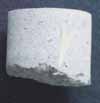
Wire mesh can end up at the bottom of the slab. This core
sample of a wire-mesh rein forced concrete slab illustrates what happens
when concrete is poured over the mesh. Rather than staying in the middle
of the slab, where it strengthens the slab, the mesh gets pushed to the bottom,
where it does little good.
found_8-1.jpg Rebar on Chairs Stays in Center of Slab: In concrete slabs, steel-bar reinforcement works better than wire-mesh reinforcement because it stays where it’s put. It’s also important to have a firm, even bed beneath the slab and to cover the substrate with a plastic vapor barrier. Minimum 2 in. between steel and ground; Bed of sand, gravel, or crushed stone beneath poly; Chairs to support rebar; #3 rebar at 18 in. o.c.
Special Considerations for Slabs on Grade
Concrete slabs need to have a firm, even, well-compacted substrate, which begins with properly prepared original ground. Remove all sod, stumps, roots, other organic matter, large rocks, and wet, mushy soil. The soil must be compacted thoroughly and evenly. If you have unstable soil, plan on hiring an engineer or ending up with a cracked, buckled slab.
Placing gravel, crushed rock, or sand before pouring the slab makes an even surface to receive the concrete. As the concrete shrinks, the slab edges want to slide toward its center. A smooth surface of sand makes it easier for the concrete to slide, reducing its tendency to crack.
A layer of sand or gravel also creates a capillary break between the ground and the slab. Sand still wicks some water, so we usually recommend placing a vapor barrier on top of it. You should compact any sub-base material well and dampen any exposed areas just before pouring the slab.
Rebar Performs Better than Wire Mesh in Slabs
Steel rebar and wire mesh both serve the same function: They add structural reinforcement to the concrete. Rebar is only slightly more expensive than mesh but easier to keep centered in the slab. If mesh is properly placed, it should do just as good a job of strengthening the concrete as rebar.
Reinforcement should stay centered in the slab and not trip concrete workers as they move about. However, if the reinforcement is wire mesh, there’s no way to avoid trampling it while placing the concrete. So the mesh gets embedded in the sand beneath the slab. Although it’s not impossible to keep the mesh centered uniformly in the slab, it's difficult.
Placing a grid of #3 rebar at 18-in, centers provides adequate slab reinforcement and places for nimble feet to step. Supporting the bars on metal “high chairs” or precast concrete cubes (“dobies” where I live) keeps them in the proper position as concrete is poured over them. The cost difference between mesh and rebar is almost negligible, and the reinforcement ends up where it belongs (drawing and photo, facing page).
Reinforcement falls into two main categories: structural and shrinkage/temperature. Structural reinforcement provides strength to resist bending, compression, or tensile loads. Shrinkage/temperature reinforcement reduces the concrete’s tendency to crack as it dries or as it contracts or expands due to temperature changes.
For the latter, chopped fibers of polypropylene, nylon, steel, glass, palm fronds, or the like may be added to the concrete mixture. Because the fibers are automatically distributed throughout the concrete during mixing, there are no concerns about proper placement. For most slabs on grade that require no structural reinforcement, fiber reinforcing can be placed in the mix at the batch plant.
Control Joints Help Control Cracking
Shrinkage cracks appear in any slab. But you can keep them small and govern where they appear by building in control joints. A control joint works like perforations in a piece of paper. The joint is a line of weakness in the slab that eventually becomes a crack.
If you place the joints at 15-ft. to 20-ft. intervals, most cracking occurs along the joints. For large industrial or commercial slabs, control joints usually are sawn into the concrete. On smaller jobs it may not be worthwhile to bring a concrete saw on site. In such cases, long pieces of plastic extruded in T-shaped cross section can form the joints. Concrete finishers force the stem of the T into the slab. To ensure that cracks occur at the control joints, their depth should be at least one-quarter of the slab’s thickness.
Tips on Placing and Working Concrete
Concrete-form construction is beyond the scope of this article. But when you build forms, build them stronger than necessary. Brace them well; expect to climb all over them while carrying an ornery vibrator.
Secure anchor bolts and other inserts to the forms in their proper locations before the pour. (Poking bolts into wet concrete disturbs the aggregate and gives a weaker bond than pouring the mix around the bolt.) If you use a form-release agent, apply it to the form boards only, not to the reinforcement.
Always place concrete as close to its final position as possible. When concrete comes out of the chute or the pump hose, it should not free-fall more than 4 ft., or clatter off the rebar or forms (drawing above). Either of these conditions can cause the coarse aggregate to separate from the rest of the mix, resulting in concrete that’s not uniform. Pre venting this condition in tall walls or columns usually requires that a concrete pumper dispense the concrete from a hose, which can maneuver close to the bottom of the forms.
Building codes require vibrating all structural concrete to eliminate voids. To do this properly, turn the vibrator on and insert it into the concrete as quickly as possible. To vibrate the first lift poured, insert the vibrator all the way to the bottom for 10 seconds. Then withdraw it slowly, about 3 in. per second. The goal is to allow all of the trapped air bubbles to get out of the concrete. The bubbles move up slowly; if the vibrator head moves faster than they do, they will remain trapped. Vibrate any additional lifts the same way, but extend the end of the vibrator about 6 in. into the previous lift.
The vibrator influences a circular area of concrete, whose size depends on the power of the tool. These circles of influence should overlap. Use a regular pattern and consolidate the concrete. don't insert the vibrator at haphazard angles or use it to move concrete in the forms.
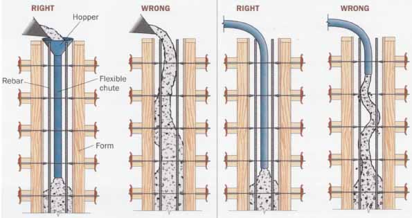
The Right Way and the Wrong Way to Place Concrete: If
concrete is dropped from a height greater than 4 ft. into a form or permitted
to fall freely over reinforcement, the aggregate can separate from the concrete
or honeycomb at the bottom. When filling forms from a chute, use a hopper
to deliver concrete to the bottom of the forms. When using a pump, feed the
hose to the bottom of the form.
Keep the Concrete Wet and Warm
Builders always want to hurry to strip the forms, but leaving them in place a few days holds the moisture in the concrete. A week of wet curing would make any engineer happy. Keep the concrete wet by covering it with plastic or wet burlap, or with spray from a fog nozzle. Slabs also can be flooded. Curing compounds that seal in moisture when sprayed on concrete are available.
Rapid drying or freezing severely reduces concrete’s strength and results in weak slab surfaces. A little time invested in proper curing protects the finished product you worked hard for.
For further information, the American Concrete Institute publishes several references and the model code, ACT 318-89. The Aberdeen Group® offers several publications and references intended for contractors and builders. “Design and Control of Concrete Mixtures” by the Portland Cement Association offers 200 pages of information including mixing, placing, finishing, and testing.
Understanding the Principles of Concrete-Block Construction
Reinforced concrete-block construction can produce strong, durable walls efficiently. But too few masons really understand the principles involved in the trade. In this type of construction, three components form the structural system: the blocks and the mortar that holds them together, the reinforcement, and the grout, which is used to fill in the cores in the concrete block.
Grout is a mix of fine gravel, sand, cement, and water. In some areas (not California), mortar is used instead of grout in block cores. However, grout contains coarser aggregate than mortar, which makes it stronger. Building codes require each cell that contains reinforcement to be filled with grout. In seismic zones 3 and 4 (almost all of California and the West Coast), this rule means filling at least every sixth vertical cell (every 4 ft.) and grouting a bond beam at the bottom, middle, and top of an 8-ft. wall. (Bond-beam blocks are made with space for horizontal rebar to lay in them; a course of these blocks, when reinforced with steel and filled with grout, forms a bond beam.) Additional bars at openings, or where required by the designer, often decrease the spacing to 32 in. or even 24 in. Grouting all of the cells is usually easier than trying to block off the cells where grout is not required, so most walls we see are solid-grouted. In essence, concrete blocks or withes of brick just serve as the forms for a fine-aggregate concrete (grout) wall. Your wall should solidly attach to the footing and act as a monolithic unit, not a stack of separate blocks. Also, cores should be grouted after the wall is built, not as you go, which would mean cold joints.
TIP: Rapid drying or freezing severely reduces concrete’s strength and results in weak slab surfaces.
Clean-Outs Ensure that the Wall Bonds to the Footing
Openings at the base of cells that receive grout allow you to remove construction debris before pouring. When all of the blocks are laid, you can remove the mortar droppings, nails, tape measures, cellular phones, and the like that have fallen to the bottom of each cell. (Initially pouring an inch or so of sand at the base of the clean-out prevents fresh mortar from sticking to the footing. These chunks de crease the bond between the grout and the footing.) Then, seal the clean-outs before pouring the grout, and let the mortar set a few days (to prevent blowouts) before the grout is poured. Building codes require clean-outs in cells containing reinforcement if a grout pour will be more than 5 ft. high. For shorter lifts, you can suck debris out with a shop vacuum, although you may have trouble winding past all of those bars.
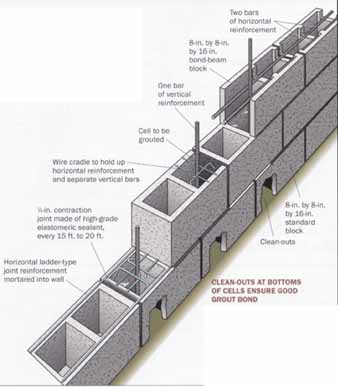
Ample Reinforcement Leaves Room for Vibrating and Has
Built-In Joints: A single horizontal bar centered in this composite
drawing of various walls would have made it difficult to vibrate the grout.
Two bars spaced apart provide greater strength and leave room for the vibrator
head to snake down to the bottom. Also, a 1/4-in. contraction joint made
of special caulking allows the wall to shrink without cracking. The horizontal
reinforcement that runs through the course of bond-beam units is continuous
across the contraction joint.
- Two bars of horizontal reinforcement
- 8-in, by 8-in. by 16-in. bond-beam block
- One bar of vertical reinforcement
- Cell to be grouted
- 8-in, by 8-in. by 16-in. standard block
- Clean-outs
- ¼-in. contraction joint made of high-grade elastomeric sealant, every 15 ft. to 20 ft.
- Wire cradle to hold up horizontal reinforcement and separate vertical bars
- Horizontal ladder-type joint reinforcement mortared into wall.
CLEAN-OUTS AT BOTTOMS OF CELLS ENSURE GOOD GROUT BOND: Clean-out blocks allow mortar droppings and debris to be removed before grout is poured, letting the grout adhere to the concrete footing. Before the pour, the face of the clean-out block is mortared back in place.
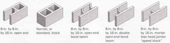
Standard Types of Concrete Block: Here are
a few of the more standard types of concrete block. There are many other blocks
made for a variety of different functions and in a variety of different sizes,
configurations, and textures.
- 8-in, by 8-in. by 16-in, open end
- Normal, or standard, block
- 8-in. by 8-in. by 16-in, open-end bond beam
- 8-in. by 8-in. by 16-in, double open-end bond beam
- 8-in. by 8-in. by 16-in. mortar less head jointor “speed block”
Ladder-Type Joint Reinforcement Is Better than Truss-Type
Joint reinforcement can be used instead of bond-beam units that contain horizontal bars. This type of reinforcement consists of two horizontal, parallel wire rods connected by cross ties (drawing, facing page). The reinforcement is placed between courses of block or brick, and the side rods get embedded in the mortar. The cross ties may go straight across or zigzag; these cross ties are called ladder and truss types, respectively.
The cross ties of ladder reinforcement should preferably align vertically with the webs of the blocks. Truss-type or zigzag-type wire reinforcement is even more difficult to align. We don’t recommend using this reinforcement in concrete-block walls because the diagonal reinforcement can block the open cell and make it difficult to insert the vibrator.
Use Pairs of Horizontal Rebar to Make Room for a Vibrator
Rather than using single horizontal bars in bond beams, which lie in the middle of the wall cavity, use pairs of horizontal bars (either smaller bars or the same size at greater spacing). This process leaves more room for the vibrator head. Designers should consider this idea, but if yours hasn’t, ask about it before proceeding. In straight runs of wall, open-end units allow grout to flow mote easily through the block cavities. Using standard units forms air gaps between blocks at head joints.
Admixture Increases Grout Bond to Block
Certain compounds react with grout ingredients to produce a gas. The gas expands, forcing the grout into the porous surface of the block cells. Several brands of admixture are available; most use powdered aluminum as the active ingredient (Grout-Aid by Sika Corp. or MB612 by Master Builders Inc.).
Most masons add the admixture once the grout arrives at the site because its working time is limited to about an hour. Although the powder may be added straight into the truck, we require it first to be thoroughly mixed with water. If clumps of powder get pumped into the wall, they can generate enough gas pressure to pop the block apart.
Vibrate Grout Twice
For grout to flow into all of the crevices in a wall, it needs to be as fluid as possible. This wet grout is poured into dry masonry and vibrated immediately. The masonry soaks up excess water. As this soaking occurs, the grout loses volume. The grout may actually shrink away from one side of the grout space. Building codes require reconsolidating the grout with a second vibrating. Vibrating a second time settles the grout fully into the cavities.
I have seen the level of a 4-ft. grout lift (the maximum height allowed) drop by 2 in. during re-vibration. It’s important to wait at least 20 minutes before re-vibrating so that excess water has time to soak into the masonry. But don't wait so long that the expanding admixture reacts completely or that the grout begins to set up. In mild weather, re-vibrate within 45 minutes to an hour of placing the grout.
TIP: For grout to flow into all of the crevices in a wall, it needs to be as fluid as possible.
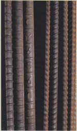
More about Concrete Reinforcement A common gauge of steel’s strength is its yield stress. When you apply stress below the yield stress and then release it, the steel returns to its original shape. But when you apply stress greater than the yield stress, the steel begins to deform permanently. The yield stress of reinforcing steel is indicated by its grade. Grade 40 means the yield stress is 40,000 psi. Most reinforcing bars are either grade 40 or grade 60. U.S. steel mills produce reinforcing bars in 11 sizes, which are denoted by numbers (see the chart below). Those numbers represent the bar’s nominal diameter in 34-in. increments. So a #4 bar is 34 in. dia. and a #18 bar is 2 1/4 in- dia. Multiplying the bar’s yield stress by its cross-sectional area gives its strength. For example, a #4 bar of grade-40 steel will withstand 8,000 lb. of force (0.2 sq. in. x 40,000 psi). A bar’s size and grade are stamped along its length, appearing in a column of symbols, letters, and numbers. The first number to appear is the bar size. For some reason, the steel grade is more deeply hidden. Grade-40 bars have no special or additional marks. Bars of grade-60 steel have the number 60 stamped as the last symbol in the column, or they have an additional rib in their deformed pattern. For the strength of a bar to be realized, it has to be held in a tight grip by the concrete. This bond strength comes from the bond between the concrete and the rebar, and it depends mostly on the concrete’s strength and the holding ability of the rebar. The combination of concrete strength and holding ability of rebar is known as development length. For a #4 grade-40 rebar, the correct development length is the distance the rebar must be embedded into the concrete so that when you pull on it with 8,000 lb. of force, the rebar stretches rather than pulls out of the concrete. The American Concrete Institute’s (ACI) model code gives formulas for determining development lengths. For “small” bars (#6 and smaller) and typical residential concrete, the development length is approximately 32 to 36 times the diameter of the bar. For more information on rebar, contact the Concrete Reinforcing Steel Institute. STANDARD REINFORCING-BAR SIZES To determine the strength of a given size of rebar, multiply its yield stress (40,000 psi and 60,000 psi for grades 40 and 60) times its cross-sectional area. [Bar size Weight per ft. Diameter Cross-sectional area] 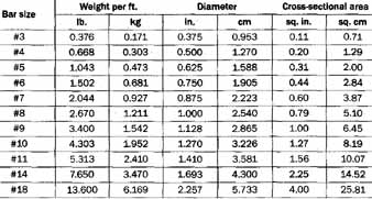
|
Vertical Contraction Joints Reduce Cracks in Long Walls
Masonry walls shrink in length and height as excess water in them dissipates. It may seem as if you’re weakening the wall, but if you don’t provide contraction joints to accommodate this shrinkage, the wall makes its own—in the form of cracks. To avoid shrinkage cracks, build long walls in segments no more than 20 ft. long.
Build each segment as if it were an individual wall, but run horizontal reinforcement continuously. Separate the wall segments about 1% in. Instead of a mortar joint between them, fill the gap with a high-grade elastomeric sealant, such as Sonolastic from Sonneborn; or Sikaflex from Sika Corp. Joints can break up a wall’s appearance, but they look better than cracks.
Using some or all of these tips will make your work easier and stronger. For further information, the National Concrete Masonry Association publishes its TEK briefs on a wealth of masonry topics.
Resources:
American Concrete Institute: ACI International
P.O. Box 9094
Farmington Hills, Mi 48331
(248) 848-3700
The Aberdeen Group
426 S. Westgate
Addison, IL 60101
(800) 323-3550
Concrete Reinforcing Steel Institute
933 N. Plum Grove Rd.
Schaumburg, IL 60173
(847) 517-1200
Master Builders Inc.
23700 chagrin Blvd.
Cleveland, OH 44122
(800) 628-9990
National Concrete Masonry Association
13750 Sunrise Valley Dr.
Herndon, VA 20171
(703) 713-1900
Portland Cement Association
5420 Old Orchard Rd.
Skokie, IL 60077
(847) 966-6200
Sika Corporation
201 Polito Ave.
Lyndhurst, NJ 07071
(800) 433-9517
Sonneborn Chem-Rex Inc.
899 Valley Park Dr.
Shakopee, MN 55379
(800) 433-9517
Prev: Introduction
Next: Working with Rebar