The place to begin understanding skyscraper structure is in Egypt— just outside of Cairo. The pyramids of Giza have stood there for 4,500 years—the longevity of their enormous bases and tapered tops a credit to a man named Imhotep, often acclaimed as the world’s first structural engineer. He calculated correctly that a thick, strong base was a critical ingredient in building tall and, relying on that premise, built pyramids that reached higher than any structure preceding them.
Imhotep’s simple building formula remained unchanged for thousands of years. Until the late nineteenth century, multi-floor structures around the world were supported on masonry walls that increased in thickness as they neared the ground. The higher they reached into the sky, the thicker their bases needed to be. This placed an effective cap on the height of buildings. as at some point floor area at the base became so monopolized by supporting walls that it was useless for any other purpose.
The idea of a skeletal frame—an internal frame of metal used to support the floors and walls of a tower—was a radical one when espoused by William Le Baron Jenney in 1884, upsetting thousands of years of building history. But its merit—particularly given the declining cost of steel—was quickly recognized, setting off the race for height that would mark the dawn of the age of the skyscraper.
The primary components of a skeletal- frame system are columns and beams. Together they transmit horizontal and vertical loads through the building while supporting secondary elements such as floor slabs and cladding. Columns run vertically and transmit gravity loads to foundations; beams are aligned horizontally and transfer gravity loads to the columns. Secondary steel beams, or girders, support the floor structure.
This new rigid-frame system served as the backbone for nearly all skyscrapers built during the first half of the twentieth century. The earliest skyscraper designers saw merit in highlighting the rectilinear nature of this system on the building’s exterior, but by the second decade of the century frames were increasingly hidden by ornamental masonry façades that added weight, but no support, to the structure. Structures like New York’s Chrysler and Woolworth buildings and Chicago’s Tribune Tower relied on a skeletal-frame system that is largely invisible from the outside.
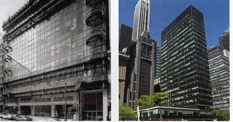
The rise of structural expressionism in the mid-twentieth century marked a “coming out” for the steel skeletons that had, to that point, been hidden beneath masonry walls. The use of glass façades allowed the boxy shape of the skeletal frame to be seen and, in the case of architectural masterpieces such as the Seagram Building and Lever House, celebrated.
The economics of steel:
p___48 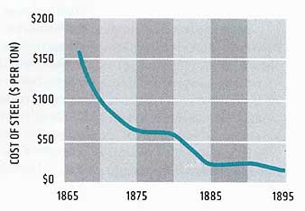
The skeletal-frame system -- Load-bearing wall buildings, common until the late nineteenth century, had walls up to six feet (1.8 meters) thick at street level and very small window openings.
COLUMNS: Vertical elements that transmit gravity loads from the floors to the foundations.
The new, steel-framed buildings featured shallow window depths and more window area. They also provided more usable space on the lower floors of the building.
Edge beams; Larger windows; More external columns.
FLOOR SLAB -- Concrete-based system that resists the vertical loads directly acting on it and transmits these loads to the supporting floor beams and girders.
BEAMS AND GIRDERS -- Horizontal elements that support the floor and transmit their vertical loads to the columns.
FOUNDATION -- Structure designed to transmit vertical loads from the columns to the earth.
How tall should it be?
Overtime, the structural systems supporting skyscrapers have changed dramatically. Each system, beginning with the earliest rigid steel frame and continuing through today’s buttressed core, has a “maximum efficient height,” above which the form becomes less than optimal from a structural perspective. However, because commercial viability is as important to developers as structural integrity, not all skyscrapers have been built to their efficient height.
EFFICIENT -- HEIGHT
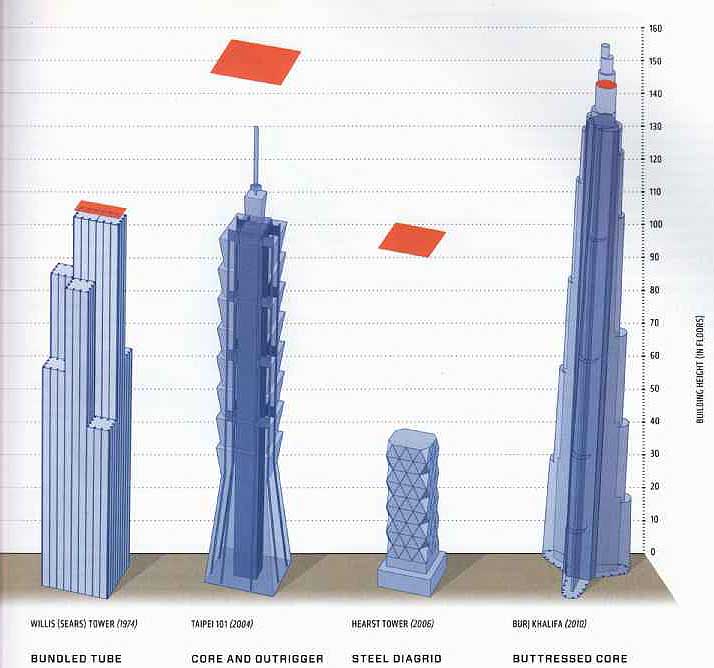
HOME INSURANCE BUILDING (IBM) -- EMPIRE STATE BUILDING (1931) -- JOHN HANCOCK CENTER (1970) -- WORLD TRADE CENTER (1972) -- WILLIS (SEARS) TOWER (1974) -- TAIPEI 101 (2004) -- HEARST TOWER (2006) -- BURJ KHALIFA (2010)
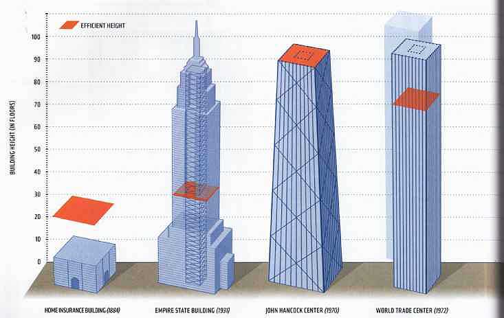
RIGID-STEEL FRAME: The earliest skyscraper structural system had an efficient height of somewhere between 20 and 30 stories.
BRACED RIGID FRAME: Bracing was added to resist lateral loads as buildings got taller, yielding an efficient height of4o stories.
BRACED TUBE: The lateral load-resisting system was moved to the building’s perimeter—pushing the efficient height to over 100 floors.
FRAMED TUBE: The framed-tube design of the World Trade Center towers, which relied on closely spaced columns, had an efficient height of 80 stories.
BUNDLED TUBE: The bundled-tube system relied on a cluster of tubes connected together to act as a single unit; it allowed better interior planning and a slightly higher efficient height.
CORE AND OUTRIGGER: The conventional load-resisting system is extended from the core to the building’s perimeter columns through the use of outriggers, raising the efficient height to 150 stories.
STEEL DIAGRID: The steel-diagrid system resists lateral shear via its diagonal members. Though harder to construct due to complicated joints, it has an efficient height of roughly 100 stories.
BUTTRESSED CORE: The buttressed-core system, devised for the Burj Khalifa, features a sexagonal core reinforced by three buttresses that form a Y-shape and allow the building to support itself.
Structural Evolution
The rigid-frame system was not exclusively a steel phenomenon. Concrete was used to frame tall buildings as early as 1903, but they were bulky affairs and rarely reached taller than 15 stories. Steel frames could reach three or four times higher—until wind loads became so great that they would jeopardize the building’s structural integrity.
Building higher than 50 or 60 stories became possible only with the development of an entirely new framing system in the mid-1960s. Tubed systems, the idea of a structural engineer at Skidmore, Owings & Merrill named Fazlur Khan, relied on a series of perimeter tubes designed to both carry the gravity loads of the building and resist the lateral loads upon it. Tried first on a modest apartment complex in Chicago, the idea would revolutionize skyscraper design around the world.
Perimeter-tube systems, expressed in either concrete or steel, relied on closely spaced exterior columns that, connected to one another by deep beams, formed a spatial skeleton for the building. Tubes could be arranged in any form whatsoever, freeing buildings from the rectilinear shape that had characterized rigid-frame systems. The strength of the perimeter structure meant that far fewer internal columns were needed, opening up the interior of tower floors dramatically.
The increased stability associated with the new tube technology allowed buildings to resist greater loads and thus rise to unprecedented heights. The four giant towers of the 1970s were all tube-based systems: the World Trade Center towers were framed-tube structures, Sears Tower was designed as a bundled-tube system, and Chicago’s John Hancock building was designed with a braced-tube exterior. Though their bracing systems varied, each featured lateral load-resisting tubes at the building’s perimeter.
While the views from the upper floors of these new supertall buildings were unmatched, not all portions of these floors enjoyed them. The perimeter tubes blocked views to varying extents: one third of the Sears Tower façade was devoted to the structure, while half of the World Trade Center façades were made up of steel rather than glass.
A new structural system was devised in the 1990s that improved upon the tube idea. In place of myriad vertical columns the building perimeter would feature a smaller number of supercolumns attached to a high-strength concrete core by massive outrigger arms that stretched horizontally across the building at various levels. The supercolumns, like the tubes before them, were attached to one another by belt walls that encircled the perimeter at regular intervals.
Over a period of 100 years, then, the structure of the skyscraper really became its architecture. Designed to work with both gravity and the wind, the modern skyscraper found itself climbing to heights never before imagined.
Steel:
The production of steel involves the melting of iron ore and the addition of various other elements, often called alloys. The mix of these alloys determines not only the hardness of steel but other properties as well. For example, the addition of chromium leaves a hard oxide on the surface of the steel, giving us what we know as “stainless steel.” In general, the different grades of steel are characterized by their “yield strength”—the stress level at which a steel member begins to bend permanently out of shape.
Ways of increasing the strength of steel have been devised over the last century, so that today a thinner steel member can provide a level of support that required a much thicker one at the dawn of the skyscraper age. Plants around the world distinguish themselves by the size and thickness of the steel they can produce, with those producing the largest steel plate generally located in Europe and Asia.
1. The first step in steel formation is a blast furnace. Fuel and iron ore are continuously supplied through the top of the furnace, while air is blown into the bottom of the chamber. The furnace produces molten metal and slag.
2. The molten metal and slag is poured into a ladle or torpedo ladle. The high-strength, high- temperature ladle is used to transport and pour the molten metal for the casting process.
3. Continuous casting transforms molten metal into a solid on a continuous basis. In this process, molten steel flows from a ladle through a “tundish” into the mold. The tundish can also serve as a refining vessel to float out impurities into the slag layer. After the mold the cooling steel is passed through withdrawing rollers.
4. The steel reheat furnace is used to raise the temperature of the steel to 2,200 to 2,400 degrees Fahrenheit (1,200-1,300 degrees C) in order to “hot roll” the steel in a desired shape and thickness. The yield strength of steel decreases as the temperature rises, and large deformations can thus be obtained with modest roll forces.
5. The hot steel is passed through a rolling mill to shape the steel, using rollers con figured in different axes to produce shapes ranging from flat plates to I-beams and C-channels.
Concrete:
Concrete is a construction material made up of cement, aggregates (normally a coarse material like gravel, limestone, or granite, plus a finer additive like sand), water, and various chemical admixtures. Use of concrete dates back to ancient times, when lime was a common element in mortar. Its composition has varied greatly over time, and added ingredients have included materials as wide-ranging as blood (for frost resistance), hair (to reduce cracking), and volcanic ash (to accelerate hardening).
The use of concrete in skyscrapers was limited until the introduction of reinforced concrete—i.e., concrete strengthened by the insertion of steel. Though it performs well under compression, concrete performs poorly under tension. Steel, in contrast, performs equally well under either condition. Combining the two initially took the form of inserting straight steel bars into concrete (with metal stirrups to clip them on); soon after, twisting steel bars were introduced to increase the adhesion of the steel to the concrete itself.
While reinforced concrete was used heavily in the construction of multistory residential buildings (generally 10 to 20 stories) through the first half of the twentieth century, it was only with the development of new forms of concrete in the second half of the 1900s that concrete came into its own as a preferred material in skyscraper construction. Stronger steel was introduced to reduce the weight, and hence increase the efficiency, of tall towers. New forms of high-strength concrete allowed tower columns to be designed thinner than previously. And the introduction of high-performance concrete, which cured, or reached its strength, faster than previous forms of concrete, vastly sped up construction on building sites using it.
Today the advantages of using these two materials in tandem has been further amplified by the practice of casting concrete around pre-tensioned steel tendons. The cured concrete, undergoing a chemical reaction, bonds to the steel tendons; when the tension is released it’s transferred to the concrete as compression b static friction. Most pre-tensioned concrete elements are prefabricated in a factory and transported to the construction site by truck—thus limiting their size. Similar results can be achieved by “post-tensioning concrete,” or by adding tension to the steel tendons after pouring the concrete.
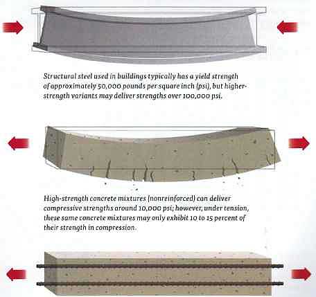
Steel-reinforced concrete -- While concrete is relatively cheap and can easily take the shape of any form, it shows strength only when compressed. If a concrete structure is pulled apart, it wants to crumble. Steel, on the other hand, has the same strength whether compression or tension is applied. Reinforcing concrete by embedding steel within it improves the behavior of concrete in tension by taking advantage of steel’s strength in both directions.
The term “rebar” is commonly used as shorthand for “reinforcing bar”—the cylindrical steel bar that is used to reinforce concrete. Often the rebar will be ridged, in order to adhere better to the concrete. Regardless of its form, however, rebar can still be separated from the concrete in high-stress conditions. As a result, it may be bent and hooked to other rebar at its end—to lock it more securely into place.
Structural steel used in buildings typically has a yield strength of approximately 50,000 pounds per square inch (psi), but higher- strength variants may deliver strengths over 100,000 psi.
High-strength concrete mixtures (non-reinforced) can deliver compressive strengths around 10,000 psi; however, under tension, these same concrete mixtures may only exhibit 10 to 15 percent of their strength in compression.
Reinforcing concrete can significantly improve its performance. The addition of high-strength steel or carbon-fiber reinforcement, as well as the incorporation of quartz or silica aggregate, can help concrete mixtures reach compressive strengths in excess of 100,00 psi.
Mixed-Use Structures: Concrete and Steel
Until the late twentieth century, the structure that supported tall buildings was made from either steel or concrete. Pre-1900 skyscrapers generally relied on steel frames, while the introduction of reinforced concrete at the turn of the century offered builders another option. In general, developers of commercial buildings chose steel and those developing residential buildings chose concrete.
Concrete was the material of choice for residential construction for a variety of reasons. It’s far better than steel at sound absorption, and reducing the transfer of noise between individual units of a hotel or apartment building was an important consideration to developers of these buildings. It’s also more fire-resistant, an important characteristic in an age when fires were a frequent occurrence and fire prevention technology was more primitive than his today.
But concrete has limited floor spans—not ideal for office buildings, in which larger, more flexible floor plates are desired (and proximity to a window is less important than it’s in homes). Both commercial developers and their tenants have always put a premium on open, column-free space—which can more easily be adapted to the needs of a variety of office users overtime. Steel, which can support much longer individual spans than concrete, was therefore the material of choice for office construction throughout most of the twentieth century. The demands of modern technology—e.g., underfloor air-conditioning, telecom, and power — highlight the continuing value of flexibility and openness in the design of tower floors.
Advances in concrete technology have, however, blurred the relative advantages of the two materials in skyscraper construction. The development of high- strength and high-performance concrete has meant that concrete buildings can be designed with skinnier columns and can go up much faster than ever before—both helping to offset the cost of construction. In addition, new technologies allow concrete to be pumped higher and higher. In 1960, the tallest concrete building was 20 stories; 50 years later, concrete was the material of choice for some of the world’s tallest buildings—including the Petronas Towers and the Burj Khalifa.
The rise of the mixed-use building: Historically speaking, most of the tallest skyscrapers in the world were office buildings. This remained true as recently as the year 2000. Over the last decade, however, there has been a significant shift toward residential uses. Today less than half of the 100 tallest buildings in the world are used solely for office purposes.
THE WORLD’S 100 TALLEST BUILDINGS (BY FUNCTION)
• MIXED USE/OTHER
• HOTEL
• RESIDENTIAL
• OFFICE
Anatomy of a hybrid: A mixed-use tower, such as the Bloomberg Tower in New York (also known as 731 Lexington Avenue), generally employs steel framing for the lower, office portion of the building, to ensure maximum spans from column to column. A transfer floor is then built to support the residential tower above, which features a shorter distance between columns and is framed in concrete to ensure better sound-proofing. The distance between columns in the office portion of the Bloomberg Tower is 30 to 35 feet (9 to 10.5 meters); the distance between columns in the residences is 15 to 20 feet (4.5 to 6 meters).
Bloomberg Tower under construction
The ability to build high with concrete has facilitated the rise of the mixed-use building—one that serves both office and residential purposes. Indeed, many of the world’s tallest structures—and even smaller ones, like the Time Warner Center in New York—now seamlessly blend the two uses along with many more, including retail, recreation, and entertainment. Office and retail spaces are usually found in the lower portion of a building, with hotel or residential units—both of which lend themselves to smaller floor plates and better views—located toward the top.
The construction of mixed-use buildings is an art in itself. Typically steel will be used to provide the long spans necessary for the office and retail portions of a building, with concrete used to construct the residential or hotel portions of the structure. Because the design and relative sizes of the floors vary dramatically from one to the other, a transfer floor will generally be needed to shift the loads from the columns in the top (typically concrete) section of the building to a new grid of columns located in slightly different places in the lower (typically steel) portion.
RESIDENTIAL (CONCRETE) FLOORS---Concrete-framed structures in residential skyscrapers often have much closer column spacing than steel-framed buildings. Shorter spans between columns don’t present as much of a problem with interior layouts, since residential floors are divided into much smaller rooms than typical office floors.
OFFICE (STEEL) FLOORS Steel-framed office structures allow much longer unsupported spans between columns—typically up to 45 feet (14 meters). This, in turn, affords the architect and tenants more flexibility in laying out office floors by offering larger, open spaces or ample room for division into offices by non-load-bearing walls.
Gravity Loads
The structural system chosen to support a given building is primarily a function of the loads to be placed upon it, and will almost always be designed in conjunction with its foundation. A variety of loads are taken into account by structural engineers during the design process, including the dead load—the weight of the building alone—and the live load—the weight of the people and the furnishings that will populate the structure.
Dead and live loads are important in calculating what’s known as the “gravity load”—the weight pushing down from the building into the earth below it. This is sometimes referred to as the “vertical load,” although this phrase technically includes loads pushing upward (sometimes called “heave” or “uplift”) that arise as a result of either wind moving against a building’s roof or groundwater or seismic energy pushing the entire structure upward from the soil.
Gravity loads are transmitted through a building’s columns, which may be located on its perimeter or internally, including through its core. Typically each column will land on a footing, which acts to spread the gravity load across an area wider than the base of the column. These may often be attached to a raft structure, which often acts as the top of the piles, caissons, and other foundation elements.
Height and gravity -- As the height of a building (and the amount of its “dead load”) doubles, the total gravity load roughly doubles as well.
Floor slabs take dead and live loads on the floor and transmit them to floor beams.
Floor beams transmit these dead and live loads to vertically oriented columns.
Columns transmit these gravity loads to the foundation.
Transfer beams and floors -- Gravitational forces have changed little since Sir Isaac Newton’s day: they still pull items straight down to the earth. Building loads from the upper floors of a tower will typically travel straight down a series of columns directly to the building’s foundation—unless they are interrupted.
For any number of reasons, regular column spacing may not be desirable on a particular floor of a building. There may be a need for more open space—e.g., in a lobby or auditorium area—or there may simply be a desire for a less cluttered appearance on a particular floor.
But the all-important columns can’t be interrupted or removed without making sure that the load they are carrying has somewhere to go. In cases like these, transfer beams—horizontal members spanning the roof of the space to be opened—will be used to shift the load from the columns above the floor to others on the edges of the open space. The size of the opening, or column-free space, will generally dictate the thickness and strength of the transfer beam required.
The concept of transferring load can also be applied on a broader scale to the entire weight of a building. When a structural engineer needs to shift the footprint of all the columns- either because the size and layout of the floors are changing or because spacing between the columns needs to change-he or she will design a "transfer floor," a trusslike structure that carries the gravity loads from the columns above to a new set of columns below the transfer floor. This is often the case with mixed-use buildings whose floor layouts change significantly between designated commercial and residential floors.
Lateral Loads
Few people outside the engineering or architectural professions realize that horizontal, or lateral, loads, rather than vertical ones, are what really drive skyscraper design. As building height grows, the lateral loads upon a structure grow exponentially, while the gravity loads simply increase arithmetically. The biggest challenge a designer of a supertall building faces, therefore, is how to brace the building to withstand lateral loads.
Lateral force upon a tall building can take several forms. It can arise from a seismic event, which sends shock waves out from its epicenter. Most commonly, however, it stems from the force of the wind as it moves past a particular building. Wind pressure is determined by many things, including the wind’s speed and direction, the geometry of the building, and the shape and proximity of the structures upwind of the building.
Wind itself is rarely uniform; it’s composed of numerous eddies of varying sizes and behavior as it moves past the earth’s surface and past nearby structures and topography. As a result, its force can vary dramatically over fairly short distances and time intervals. In general, its speed generally increases significantly with height, though it also tends to behave more predictably (i.e., fewer gusts) at higher levels.
Assessing the wind is critical to building engineers. Too much movement could undermine the integrity of the beams and columns and lead to deformation of the structure, possibly causing damage to building components and discomfort to building occupants. The skin of the building, known as “cladding,” is vulnerable to sudden gusts of wind, because it’s not load bearing and is attached fairly simply to the structural elements beneath it. In addition, wind loads at the base of a tower can have a significant impact on people and objects at street level, creating an uncomfortable, and sometimes dangerous situation for pedestrians.
Calculating wind loads is the law in many places. However, these regulations tend to assume simple rectilinear structures and don’t take into account the dynamic nature of wind behavior, putting the onus on the design team to undertake e sophisticated modeling.
Height and wind -- As a result of a doubling in height, the total lateral load acting upon a building will increase by a factor of four—or by the amount of the increase squared. As buildings get taller, wind loads increase much more significantly than gravity loads.
Wind loads act on the surface of the curtain wall.
An imbalance of lateral loads between the upwind and downwind faces of the building results in an overturning, or uplift force, on the windward columns and foundation.
The curtain wall is attached to the floor beams, which absorb the load.
The floor beams transmit the load to vertical columns or through cross-bracing.
Wind Design
To minimize building costs and maximize revenues, skyscrapers generally take the shape of squares or rectangles. These are not particularly aerodynamic shapes, and theft bluntness results in a wind phenomenon called “vortex shedding.”
As wind meets a rectangular skyscraper it pushes on the flat face of the building before flowing around its sides, where eventually it separates from the face of the structure. The difference in pressures on the front and back faces of the building gives rise to vortices, or spinning eddies of wind, that flow downstream from the building. The vortices pull and push the building in a direction perpendicular to the wind at frequencies that can become dangerously self-sustaining.
To minimize vortex shedding, skyscraper designers do everything in their powers to confuse the wind. Orienting the building so that the longer face of the structure is parallel with prevailing winds can help. Chopping or rounding off corners of a building can likewise make it more aerodynamic. Roughing up the corners of the building through the careful placement of balconies or stepped corners can help by disturbing or delaying the formation of strong vortices.
Bigger architectural statements can also address the problem. Placing a twist in a building can “confuse” the wind by preventing resonant vortex shedding along a building’s height. Likewise, rotating a building can minimize the wind load from the prevailing direction. For example, the curvilinear nature of the Swiss Re (“Gherkin”) Tower in London generates pressure differences at its face that minimize wind loads. Punctuating the building’s surface with an opening, such as the Shanghai Financial Center’s trapezoidal void, can also serve to minimize the force of the wind upon a building.
To determine the best building configuration in a particular location, comprehensive wind-tunnel testing is done early on in design. The testing determines the strength and behavior of the wind both at the building site and in the areas around it, particularly at street level. It can also provide other useful information, such as the likely concentration of exhaust pollutants in the building’s air intake system.
Wind-tunnel testing is an iterative process. Tall building designs are refined and tested repeatedly on the basis of test results—to the point where some skyscraper engineers now refer to their buildings as having been “designed in a wind tunnel.” Far from a nice to have set of data, the results of wind- tunnel testing represent an integral part of modern skyscraper design.
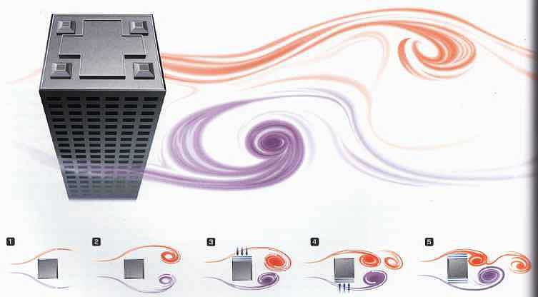
1. Wind hits the face of the building and proceeds to flow around its sides.
2. On the downwind side of the building the wind flow separates from the building face.
3. At certain wind speeds, vortices or eddies of wind are generated.
4. As these vortices “shed” from the building an imbalance in forces occurs on the sides of the building.
5. Vortices alternately shedding from the building in a resonant condition can cause extreme side-to-side motions and forces on the building.
Aerodynamics -- Aerodynamics are a major consideration in the design of supertall skyscrapers today. Structural engineers will test many shapes and configurations to determine the optimum skyscraper design. Streamlined shapes, as well as twisting forms and rough or obstructed corners, can all serve to limit vortex-shedding behavior that can undermine the integrity of tall towers.
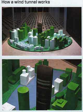
How a wind tunnel works
Most municipal building codes address permissible wind loads on new buildings. But because they are based on generic-shaped buildings, under generic conditions, they often fail to account for the unique aspects of individual tower designs— including the aerodynamic impacts of the building’s shape, the effect and influence of adjacent buildings and local topography upon the wind, and the dynamic effects of wind directionality and localized airflows.
For this reason, building codes permit and often encourage wind- tunnel tests to be performed to evaluate a proposed building’s performance under actual design conditions. The costs of such a study, while not insignificant, pale in comparison to the savings in cladding and structure that often result—sometimes in the millions of dollars. In addition, wind-tunnel testing confirms that the architect’s vision can be safely realized, and thus offers protection against future litigation.
The first step in wind-tunnel testing involves construction of a replica of the building being tested and all buildings within a half-mile radius of it, typically on a 1:400 scale. The replica is placed on a rotating platform in a computer- controlled tunnel that features a fan capable of simulating a 60 mph (100 km/hr) wind. Thousands of sensors are placed on the model.
Wind flows that mimic natural wind in the area, including a realistic distribution of gust speeds, are then directed at the model. As the direction, angle, and strength of the wind changes, computers record both wind resistance on the building and wind conditions at the bases of it and other buildings in the area. Smoke is often used to vortices easier to see.
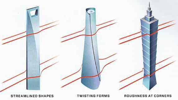
STREAMLINED SHAPES -- TWISTING FORMS -- ROUGHNESS AT CORNERS
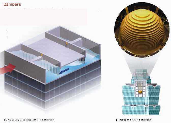
Dampers: In many tall buildings mass dampers located near the top of the building act as a pendulum to shift weight around to counteract the forces of the wind against a building.
TUNED LIQUID COLUMN DAMPERS -- The Comcast Center in Philadelphia employs the world’s largest tuned liquid damper. Holding 300,000 gallons (1.1 million liters) of water, its U-shaped tank allows the water to oscillate freely at the natural frequency of the structure.
TUNED MASS DAMPERS -- Fighting Sway While most dampers are hidden somewhere high in the building, the 728-ton (660-metric-ton) golden tuned mass damper of Taipei 101 swings in full view of patrons of the building’s restaurants and observation deck on the eighty-fifth, eighty-sixth, and ninety-first floors.
Wind loads are a problem for skyscraper designers, but not necessarily for structural reasons. Movement back and forth at high levels rarely endangers a building’s steel or concrete structure, but it does have the ability to induce motion sickness in humans living or working on those floors.
How far buildings are allowed to move back and forth is typically a function of how much movement people can tolerate—i.e., at what point a building’s sway causes discomfort to its inhabitants. In the United States, it’s common for tall buildings to be designed to sway no more than i/ of their height. Using this criterion, the new 1 World Trade Center— under construction in lower Manhattan—would be permitted to sway just over three feet (one meter) at the top of the building.
A variety of techniques are used to limit the sway of a skyscraper. Bracing, often used to tie together the building’s vertical and horizontal structural members, can take many shapes and sizes: K-bracing and V-bracing can commonly be seen on the outside of some skyscrapers. In areas of seismic activity, fluid viscous dampers often supplement bracing as a sort of shock absorber, dissipating seismic energy and reducing building displacement.
But really tall buildings demand more than just bracing and internal shock absorbers. Increasingly they rely on what are known as “mass dampers”—large structures placed at or near the roof of a building that function like pendulums to shift weight in the opposite direction from the way that the wind is pushing the building.
The earliest mass damper consisted of a large hydraulically driven weight called a “tuned mass damper.” The Citicorp Building in New York, at 59 stories, was one of the first buildings in the world to feature one. Subsequently, “sloshing” or “liquid” dampers were developed. Large tanks holding thousands of gallons of water, they allow the weight of the water to push in the direction opposite to that of the building’s movement—naturally counteracting its motion.
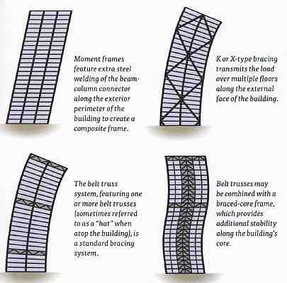
Bracing: Lateral bracing provides stiffness to the building and resists movement from wind and other lateral loads. Braced-bay systems are the most visible type of lateral bracing. They comprise diagonal, cross, K, and eccentric bracing arrangements. Other systems include braced cores, shear walls constructed from reinforced in-situ concrete, and rigid, jointed, moment-resisting frames.
- Moment frames feature extra steel welding of the beam-column connector along the exterior perimeter of the building to create a composite frame.
- K or X-type bracing transmits the load over multiple floors along the external face of the building.
- Belt trusses may be combined with a braced-core frame, which provides additional stability along the building’s core.
- The belt truss system, featuring one or more belt trusses (sometimes referred to as a “hat” when atop the building), is a standard bracing system.
Today dampers of one sort or another are more common than ever before as a part of tall-building technology. The new Comcast Building in Philadelphia features a “tuned liquid column damper” that features water moving in a column—rather than a tank—configuration. One Rincon Plaza, a new residential building in San Francisco, features a “tuned liquid mass damper” that comprises two 5,400 gallon (20,440 liters) tanks. And Taipei 101, for six years the world’s tallest building, features perhaps the most spectacular damper of all—a gold orb that sits on the ninety-first floor and constitutes a prominent part of the building’s architecture.
Citicorp scare:
The Citicorp Tower, in Midtown Manhattan, opened in 1977 as something of an engineering wonder: its 25,000 tons (22,700 metric tons) of steel rest on four nine-story stilts placed in the middle of the building’s sides, allowing it to cantilever over a church on the same block.
Soon after its opening, a Princeton engineering student contacted the structural engineer, William Le Messurier, to ask whether the columns were in the right place to best resist wind loads. In revisiting his model, Le Messurier realized that the welded joints he had specified to hold bracing in place had been replaced, during the construction process, by bolted ones. After doing further wind-tunnel testing, he also realized that his staff had never considered the possibility of non-perpendicular winds (called “quartering winds”)—and that he had a big, 59-story problem on his hands.
Le Messurier quietly let Citicorp and its lawyers know about the problem, then came up with a plan to stabilize the building. First, emergency generators were brought in to ensure that the mass damper atop the building—a critical component in fighting wind load—would not lose power. Then Le Messurier developed a plan to weld thick steel plates over the 200 questionable joints. Next he put a form of transponder on individual building components to monitor their stability via a real-time telecom connection. Then he hired weather experts to predict wind forces four times daily. Finally he worked out an elaborate evacuation plan with the Red Cross— just in case the worst came to pass.
The welding work was undertaken in off-hours so as not to alarm the building’s tenants. Drywall crews and carpenters worked from 5 to 8 p.m., welders from B p.m. to 4a.m., and cleanup laborers from 4 a.m. on. Working seven days a week, the welding job was only partially complete by the time Hurricane Ella took aim at New York in early September of 1978—but she ultimately headed out to sea and the job was finished in October.
Previous: Foundations
Next: The Skin