Active Fire Protection
Active fire protection systems include standpipe, sprinkler, and spray systems designed to extinguish the fire outright or control the fire by delaying its damaging effects. Types of firefighting media include water, foams, inert gases, and chemical powders.
Active fire protection systems are extremely effective in containing and fighting a fire if they are designed and maintained so they work properly. These systems require regular inspection, testing, and maintenance. Poor maintenance leads to a false sense of security and lack of proper protection when the system is needed under an emergency situation.
Standpipe Systems
A standpipe system is an internal piping network connected to fire-hose stations that are used to rapidly suppress a fire. Fire fighters can use hoses connected to the standpipe system or connect their hoses to valve outlets near the fire. Firefighters have great difficulty fighting fires from the ground when flames and smoke are visible above the fourth floor of a building. So, standpipe systems are mandated in buildings where it may be difficult for the fire department to adequately pump water on the fire (e.g., in buildings that are over six stories or 75 ft in height). A standpipe system also provides water that trained occupants or employees can manually discharge through hoses until the fire department arrives.
Piping in a standpipe system runs vertically (up and down) and horizontally (side to side) throughout the building.
The standpipes running vertically are usually called risers. The risers are usually located in the staircase enclosures or in the hallways in the building. This piping system supplies water to every floor in the building.
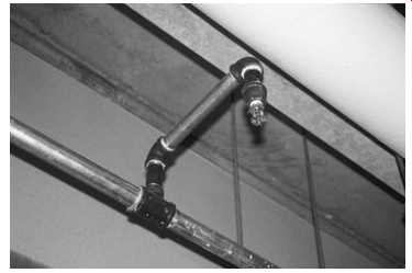
At selected locations in the building, the standpipe is connected to a hose. The hose is usually stored on a quick release rack called a hose reel. Fire-hose and reel stations are strategically positioned throughout the building. Gate valves control these connections. The occupant or firefighter must manually open the gate valve to open flow to the hose. A nozzle is attached at the end of the hose. The nozzle is used to direct the stream of water from the hose.
The hose and nozzle must be easy to reach at all times.
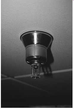
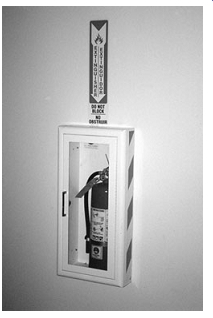
The hose outlets are located so that every part of the building may be reached with a hose stream. The maximum length of a single hose line is 125 ft. Sometimes the hoses are installed in cabinets. If the hose is installed in a cabinet, it must be labeled "FIRE HOSE.” When the hose outlets are not easy to see, signs should be posted telling where the hose outlets are located. (See imgs -3 and -4.)
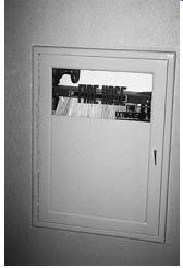
img. 3 A properly marked fire hose cabinet (closed).
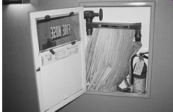
img. 4 A typical fire hose outlet and release rack connected to a standpipe
A standpipe system may be combined with an automatic fire protection system. For example, a standpipe system and a sprinkler system may be installed in the same building. The standpipe and the sprinkler systems may even share the same water supply and riser piping. The top of the standpipe riser extends up onto the roof. Hose connections are attached to the top of the standpipe riser. These three connections make up the roof manifold. The roof manifold is used when extinguishing fires on the roof. It is also used when testing the water flow in the standpipe.
Types of Standpipe Systems
Several types of standpipe systems are approved for use. The four common types are briefly described in the following.
Wet Standpipe
This system always has water in the piping.
The water in the system is always under pressure. In some cases a fire pump may be used to increase the water pressure.
The wet pipe system is the most commonly used standpipe system. It is used in heated buildings where there is no danger of the water in the piping freezing. Any part of the stand pipe system that is exposed to freezing temperatures should be insulated. It is very important that the water in the piping does not freeze. Frozen water may prevent a standpipe system from working.
Dry Standpipe with an Automatic Dry Pipe Valve
This system is usually supplied by a public water main. Under normal conditions there is no water in the piping. Instead, there is air under pressure in the piping. A dry pipe valve is installed to prevent water from entering the standpipe system. The dry pipe valve is designed to open when there is drop of air pressure in the standpipe. When a hose is opened it causes a drop in air pressure in the standpipe system. Then the dry pipe valve automatically lets water flow into the standpipe. A control valve is installed at the automatic water supply connection.
This valve should be kept open at all times to supply the stand pipe system. This system is usually installed in a building that is not heated.
Dry Standpipe with a Manual Control Valve
This system is supplied by a public water main. Under normal conditions this system has no water in the piping. The water is not allowed into the standpipe until a control valve is manually operated. The control valve remains closed until a fire occurs. This system is usually used in a building that is not heated.
Dry Standpipe with No Permanent Water Supply---Under normal conditions, this system has no water in the piping. Water is pumped into the standpipe system by the local fire department.
The water is pumped in through the Siamese connection (see Siamese connection as follows). This system cannot be used unless water is supplied by the fire department. A sign must be attached to each of the hose outlets. It should read "Dry Standpipe for Fire Department Use Only." This system is usually used in a building that is not heated.
Classes of Standpipes Systems
Standpipe systems are classified depending on who is expected to use the system. The three classes are briefly described in the following.
Class I This system is designed for use by professional fire fighters. For example, fire department personnel use the system. The fire hoses in these systems are 2 1/2 inches in diameter.
The large hose diameter makes it difficult to control the stream of water from the hose.
Class II This system is designed for use by the occupants of a building. The hose and nozzle are connected to the standpipe.
They are ready to be used by occupants in case of a fire. The hose is 1 1/2 inches in diameter. The hose stream is easier to control than the Class I hose.
Class III This system may be used by either professional firefighters or by occupants of the building. The hosing may be adjusted to either 1 1/2 or 2 1/2 inches in diameter. Attaching special reducing valves to the hose line does this.
Automatic Fire Protection Systems
Studies by various federal and state agencies and private organizations suggest that installation of automatic fire suppression systems could save hundreds of lives annually, prevent thou sands of injuries, and eliminate hundreds of millions of dollars in property losses each year.
Fire suppression systems are intended to extinguish or control a fire. These include automatic water sprinkler systems and systems that use a gas agent or foam to eliminate oxygen and suffocate the fire. Smoke control systems are designed to limit the spread of smoke to maintain passable occupant egress routes for a given period of time and to aid firefighters in fighting the fire.
An automatic fire protection system provides a warning to occupants of the building, notifies emergency personnel responding to the alarm, and activates fire suppression systems to reduce the growth rate of a fire or the movement of smoke.
Typically, smoke detectors sense the presence of fire in the building. The fire control panel then sounds an alarm, shuts down air-handling equipment, disconnects power from the protected equipment, and then releases agent into the protected area.
Conventional Automatic Sprinkler Systems
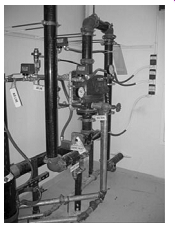
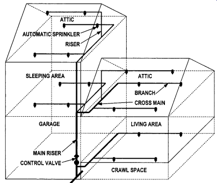
An automatic sprinkler system consists of the sprinkler heads and a network of pipes placed in a horizontal pattern near the ceiling and is designed to automatically dispense water on a fire. Examples of sprinkler system piping components are shown in img.s -5 through -10. The system is de signed to extinguish the fire entirely, or to prevent the spread of the fire.
A conventional sprinkler system is fitted with automatic devices designed to release water on a fire. These de vices are called sprinkler heads. A rise to a predetermined temperature causes the sprinkler head to open. Water is then discharged in the form of spray. When the sprinkler heads open, they are said to have fused. The sprinkler heads are fit ted at standard intervals on the piping. If more than one head opens, the area sprayed by each overlaps that of the sprinkler head next to it.
An approved automatic sprinkler system is installed in accordance with fire or building codes. It uses the proper automatic sprinkler heads for the structure's occupancy and construction, has an adequate and reliable supply of water, has been tested and shown to be in working order, and has been found acceptable to the appropriate governmental authority.
img. 5 Wet-pipe sprinkler control with pressurized water in the pipe
and mains. ( --)
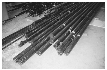
img. 6 Sprinkler pipe precut, numbered, and ready for installation.
( --)

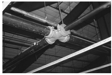
img. 7 A cross main (large pipe) connected to a sprinkler branch. (
--)
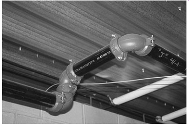
img. 8 Victaulic elbows used to connect a cross main. ( --)
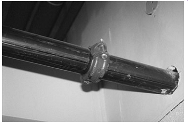
img. 9 A Victaulic coupling is a quick method of joining sprinkler
pipes. ( --)
img. 10 A Victaulic tee coupling. ( --)
Types of Conventional Automatic
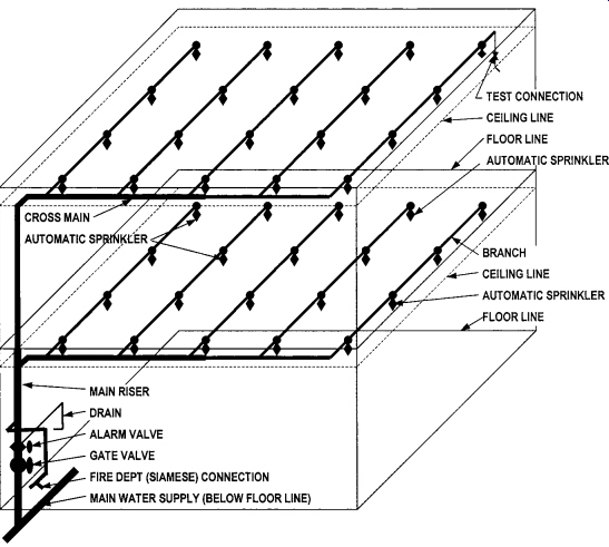
fgr. -2 A drawing of a wet-pipe sprinkler system.
Sprinkler Systems
There are several types of automatic sprinkler fire suppression systems. The following are the conventional types.
Wet-Pipe Automatic Sprinkler Systems---Wet-pipe automatic sprinkler systems have pressurized water in the pipe and mains.
Water is released when the sprinkler head is activated. Because of the potential for freezing, this system is suitable for buildings where the indoor ambient temperature is not lower than about 40°F (5°C).Wet-pipe sprinkler systems are the most common in use today. In wet systems exposed to freezing temperatures, pipes containing an antifreeze solution of water-glycerin or water-propylene glycol are connected to a water supply. The anti freeze solution, followed by water, discharges from sprinkler heads opened by a fire. This type of system is used in locations subject to freezing. Use of antifreeze solutions is limited be cause they are costly and are difficult to maintain. fgr. 2 shows a schematic drawing of a wet-pipe sprinkler system.
Dry-Pipe Automatic Sprinkler Systems --- Dry-pipe automatic sprinkler systems have pipes filled with compressed air or nitrogen. The pressure in these lines is slightly above the water pressure, and this pressure difference is what keeps the water out of the sprinkler lines. When a sprinkler head is activated, the air will begin to be released and the air pressure will drop.
As air pressure drops, water will begin to advance throughout the lines and flow through the activated head(s). The dry-pipe type is typically used in unheated buildings where there is danger that the water in the pipes would freeze and burst the pipes.
Preaction Automatic Sprinkler Systems --- Preaction automatic sprinkler systems are similar to dry-pipe except that the water first fills the pipe as an alarm is set off, providing an opportunity to extinguish the fire manually before the sprinklers open. Water is stopped at feeders (in the walls before the pipes supplying the sprinkler heads) by a valve. This valve is electronically activated by a heat-detecting device within the area, and a signal is sent to the valve and the valve opens. Water will then flow to all heads, but will only discharge through the activated heads. If there is an accidental break of a sprinkler line, water will not immediately discharge because the valve is holding back the water flow and not the sprinkler heads (unlike the wet-pipe or dry-pipe systems). The preaction sprinkler system is often used where the use of sprinklers could cause extensive material or equipment damage, such as in retail stores and computer areas.
Deluge Automatic Sprinkler Systems --- Deluge automatic sprinkler systems allow all sprinkler heads to go off at the same time.
This system is very similar to the preaction system, except all sprinkler heads are open. Once a heat-detecting device activates the valve, water will flow from all heads within the area. Deluge systems are generally installed in hazardous areas where extremely rapid fire spread is anticipated and that requires immediate application of water.
Automatic Sprinklers
Automatic sprinklers are devices that open automatically to discharge water when an excessive temperature is detected.
Each sprinkler is typically individually heat activated. When the heat of a fire raises the sprinkler temperature to its operating point (e.g., 165°F/75°C), a solder link will melt or a liquid filled glass bulb will shatter to open that single sprinkler. Once the sprinkler is open, water from the sprinkler pipes flows directly over the source of the heat, as shown in fgr. 3. The system works immediately upon sensing excessive temperature to prevent the fast-developing fires of intense heat, which are capable of trapping and killing building occupants.
Sprinkler heads are made of metal. They are screwed into the piping at standard intervals. Water contained within the system is prevented from leaving the sprinkler head by an arrangement of levers and links. The levers and links are soldered together on the sprinkler head. The solder is a metal alloy with a fixed melting point. Other types of sprinkler heads use a quartz bulb that expands and breaks under heat. A third type uses a solid chemical held in a cylinder that is broken by heat action.
The latest type of sprinkler head is called the "cycling sprinkler." This sprinkler head cycles water on and off depending on the temperature. When the disc reaches a temperature of 165°F, the valve opens, permitting water to flow. When the disc temperature cools, the valve closes to shut off the water. Sprinkler head installations are shown in imgs -11 through -15.
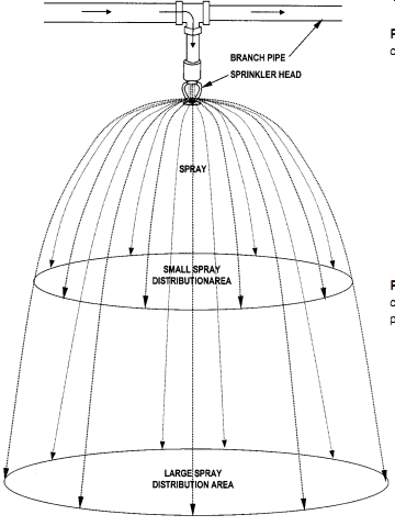
fgr. -3 Water discharging from a sprinkler head sprays over a wide
area. Distribution of the spray depends on sprinkler head height and
design.
img. 11 A sprinkler head connected to a branch before being covered
with a suspended ceiling. ( --)
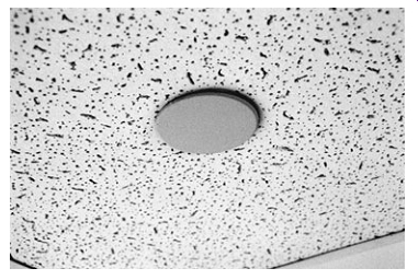
img. 12 A covered sprinkler head in a finished suspended ceiling. The
cover is used to conceal the sprinkler. It should not be painted. ( --)
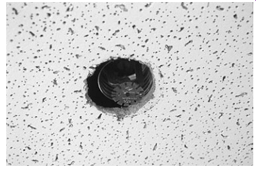
img. 13 An exposed sprinkler head in a finished suspended ceiling (cover
removed). ( --)
img. 14 A quartz-bulb pendent sprinkler head exposed in a finished
suspended ceiling. At a specific temperature, the bulb breaks releasing
water. ( --)
img. 15 A fusible link pendent sprinkler head exposed in a finished
ceiling. In this design, the water is prevented from leaving the sprinkler
head by an arrangement of levers and links. The levers and links are
soldered together on the sprinkler head. The solder is a metal alloy
with a fixed melting point. ( --)
Quartz-bulb sprinkler heads have a colored, heat-sensitive glycerin solution inside the bulb that will expand with temperature increase, causing the bulb to shatter and the sprinkler head to activate. Sprinklers with red (or orange) glass bulbs have a light hazard classification (i.e., residences, schools, offices, churches) and will activate at a ceiling temperature of 155°F (68°C), plus or minus a few degrees. Sprinklers with green (or yellow) bulbs will activate at 212°F (100°C) and are designed for ordinary hazards (i.e., laundries, manufacturing plants, and warehouses). Blue solutions in the bulb activate at around 286°F (141°C) and are designed for high hazards (i.e., aircraft hangers and occupancies dealing with flammable liquids or gases or explosives). Mauve or purple solutions in the bulb will activate at 340°F (171°C) and are rarely used; they are indicative of a very high hazard sprinkler classification.
Some sprinkler heads are designed for special situations.
Sprinkler heads exposed to corrosive conditions are often covered with a protective coat of wax or lead. Corrosive vapors are likely to make automatic sprinklers inoperative or slow down the speed of operation. They can also seriously block the spray nozzles in the sprinkler heads. They can damage, weaken, or destroy the delicate parts of the sprinkler heads. In most cases such corrosive action takes place over a long time so sprinkler heads must be carefully monitored for signs of corrosion. Care must be taken to ensure that the protective coating is not dam aged when handling or replacing the heads.
Sprinkler Operation and Layout
Sprinkler systems are installed in accordance with building and fire codes. In conventional systems, individual fire sprinklers are spaced throughout the ceiling of a building at predetermined intervals or positions. Most sprinklers have a 1/2 in discharge opening. Each sprinkler can cover approximately 100 ft^2.
Sprinkler heads are usually positioned upright, pendent (pointing downward), or sidewall (pointing sideways). Most commonly used is the pendent type, which hangs below the pipes. This allows the piping to be concealed above the suspended ceilings with only the pendent head showing. Upright heads sit on top of the pipe and the entire system is exposed to view. They are commonly used in warehouses and in retrofitting older buildings. Sidewall sprinklers are often used in small rooms where they can throw a spray of water across the entire room. In this manner, only one sprinkler is needed in the room.
Once activated, conventional sprinklers continue to run until the main valve is manually closed. This can result in excessive water damage, one of the major causes of property loss in fires. Flow control sprinklers close automatically once the ceiling temperatures are reduced. Many of these sprinkler heads are re activated if the temperature goes back up. They are not designed for use in dry-pipe systems. Regardless of the type of sprinkler head, they must be replaced after they have been activated.
A network of pipe delivers water to the sprinkler heads.
Types of pipe approved for use include the following:
• Steel pipe are approved for use in all fire suppression sprinkler applications. It is available in the following nominal diameters:
3/8,1/2,3/4,1,1 1/4,1 1/2,2,2 1/2,3,3 1/2,4,5, 6, 8, 10, and 12 in. Threaded and flanged connections are used to join pipes and fittings. Specialty compression strap-type fittings, called Victaulic couplings, make system installation easier.
• Copper tubing is the most popular water supply pipe material, but it is used less frequently in fire sprinkler systems. The thin walls of copper tubing are usually soldered to fittings. It is available in the following nominal diameters:
3/8, 1/2, 3/4,1,1 1/4,1 1/2,2,2 1/2,3,3 1/2,4,5, 6, and 8 in.
• Chlorinated polyvinyl chloride (CPVC) is a rigid plastic pipe generally approved for use in fire suppression sprinkler systems in residential and many light commercial applications. It is available in straight lengths in the following nominal diameters: 1, 1 1/4,1 1/2,2,2 1/2,3, 3 1/2, 4, 5, 6, 8, and 10 in. Solvent-cement welding, threaded, and flanged connections are used to join CPVC pipe and fittings. CPVC pipe and fittings for fire sprinkler systems are orange in color.
Alarm and Control Valves
An alarm valve and gate valve serve to control flow in the net work of sprinkler system. The alarm valve initiates an alarm signal when water flows through the sprinkler system. The gate valve opens or closes flow to the system. It should be maintained in the open position at all times. Large buildings must be protected by multiple sprinkler systems, each having an alarm valve and gate valve.
The alarm valve and gate valve must be functioning in order for the system to work. Operation of the control valves can be accomplished by the automatic fire alarm system by provision of valve tamper switches that will initiate a trouble or supervisory signal at the fire alarm control panel to indicate a closed valve. If this type of monitoring cannot be provided, the valves should be locked in the open position.
Primary Sources of Water Supply
Water for automatic sprinkler and standpipe systems must be available in sufficient quantity and at sufficient volume and pressure at all times to ensure reliable operation in the event of fire. Potential sources of water supply for sprinkler and stand pipe systems include a direct connection to the public water system, gravity tank, pressure tank, or automatic fire pump.
Where a municipal water supply cannot meet flow and pressure requirements, a reservoir or storage tank must be provided to provide a secure water supply. Approximate water application rates for various manual and automatic suppression methods are provided in Tbl. -5.
A gravity storage tank may be located on the top of a building or on a tall tower. The water in the tank is distributed throughout the sprinkler or standpipe system by the force of gravity. Pressure tanks are often used where there is enough water from a supply source, but the water pressure is too low or in tall buildings that need the extra water pressure to supply the highest line of sprinklers or the highest line of hoses.
A fire pump is a part of a fire sprinkler system's water supply in high-rise installations where the local public water system cannot provide sufficient pressure, where systems re quire high pressure at the fire sprinkler in order to flow a large volume of water (large warehouse or manufacturing plant), and where water is from a storage tank. It is designed to pump water into the fire suppression system under high pressure. The pump intake is either connected to the public water supply piping or a static water source (e.g., tank, reservoir, lake). The pump provides water flow at a higher pressure to the sprinkler system risers and hose standpipes. The fire pump starts when the pressure in the fire sprinkler system drops below a pressure threshold, such as when the sprinkler system pressure drops significantly while one or more fire sprinklers are open releasing water.
=====
TABLE -5 APPROXIMATE WATER APPLICATION RATES FOR VARIOUS MANUAL AND AUTOMATIC SUPPRESSION METHODS. COMPILED FROM VARIOUS INDUSTRY SOURCES.
Approximate Water Application Rate Delivery Method gal/min L/min Portable fire extinguisher 2.5 10 Occupant use fire hose 100 380 Residential automatic sprinkler (system dependent) 10 to 20 38 to 75 Commercial automatic sprinkler (system dependent) 25 to 72 95 to 260 Fire department single 1.5 in (38 mm) hose 100 380 Fire department double 1.5 in (38 mm) hose 200 760 Fire department single 2.5 in (64 mm) hose 250 950 Fire department double 2.5 in (64 mm) hose 500 1900
======
Supplementary Sources of Water Supply
Supplementary sources of water supply for sprinkler and stand pipe systems include manually or automatically activated fire pumps or Siamese connections. Tanks used to provide the required primary water supply to a standpipe system may also be used as a supply for an automatic sprinkler system.
A Siamese connection is a Y-shaped inlet connection for fire department use in supplementing or supplying water for standpipes and sprinkler systems. If a firefighting unit arriving at a fire finds that the sprinkler or standpipe systems is not receiving sufficient water and pressure, a fire (truck) pumper is connected to the sprinkler system to supply additional water.
Siamese connections should be provided for all sprinkler and standpipe systems in commercial buildings. Types of fire department hookups are shown in imgs -16 through -18.
Metal signs should be fastened to or above the Siamese connection indicating the area protected. Where the building has two or more frontages, additional metal signs should be those to of installed indicating the location of the Siamese connection. The installation and construction of Siamese connections should be the same as required for fire standpipe systems, except that the caps of each automatic sprinkler Siamese connection should be painted green. The entire Siamese connection of a nonautomatic sprinkler system should be painted aluminum. The caps of each Siamese connection used for combination standpipe and sprinkler systems should be painted yellow and signs should be provided.
When a fire suppression system is connected to a potable water system (in most cases, the introduction of any nonpotable water creates a potential contamination problem). In the after math of a fire department pumper truck connecting to the system, the piping must be cleaned and disinfected.
Backflow and Backflow Prevention
Poor water quality is found in most fire sprinkler systems be cause of stagnation of water and contamination from cross connections that typically occur in a fire. For example, most fire sprinkler systems are constructed with piping material that is not approved for potable water. Stagnant water in piping is subject to contamination from corrosion, which leaves a considerable amount of particulate matter and metals (e.g., zinc, cadmium, iron, copper, and lead) deposited in the water. Corrosion inhibitors and antifreeze solutions are toxic to humans and animals. Microorganisms in stagnant water in piping create taste and odor problems and can be hazardous to drink. A fire system connection to a supplemental source of water may pump a noxious or toxic substance into the fire sprinkler piping system. A loss of pressure on the potable water supply main during firefighting can allow tainted water from the fire system to enter the potable supply.
Fire sprinkler systems must have backflow prevention capabilities installed to protect the public or private potable water distribution systems from backflow of water. The backflow prevention method required is dependent upon the hazard level or classification of the fire protection system. Typically, a double check valve assembly (DCVA) or a reduced pressure backflow prevention assembly (RBPA) is required in residential, commercial, and industrial installations. Sprinkler systems using secondary sources of water or that have chemicals added should be RBPA systems, while other systems can use the DCVA method.
The backflow prevention assembly should be properly maintained, inspected, and tested annually by a licensed fire sprinkler contractor. Concepts of backflow and backflow prevention are related to a building's plumbing system and were introduced in Section 13.
===
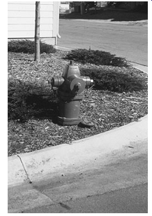
img. 16 A fire hydrant for fire department hookup. ( --)
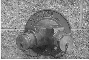
img. 17 A Siamese connection for fire department hookup to automatic
sprinkler system. These connections are a standard part of automatic
sprinkler and standpipe systems. Firefighters connect a hose to the connection
to introduce water to a standpipe or, in this case, a sprinkler system.
( --)
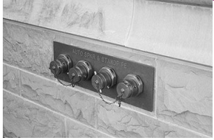
img. 18 Automatic sprinkler system and standpipe connections for fire department hookup. ( --)
===
Alternative Fire Suppression Systems
Conventional sprinklers demand high water supply rates and are associated with fixed large diameter pipe networks around the area to be protected. The necessity for large amounts of water has some inherent disadvantages: it damages most of the building's contents and interior finishes; flammable oils tend to float on the water's surface and continue to burn; it conducts electricity; and if it vaporizes into steam, it may be harmful to the firefighters. Other methods may be considered when these disadvantages are of major concern. These alternative methods include the following.
Water Mist Automatic Sprinkler Systems---Water mist automatic sprinkler systems rely upon a fine spray of water to sup press a fire. A typical system consists of cylinders of water under pressure, heat/smoke detectors, and discharge nozzles connected to a network of pipes. The mist, with its small droplets of water, is very efficient in absorbing a large amount of heat as the droplets contact the fire and is converted to steam.
This conversion to a vapor causes an expansion of over 1600 times its original volume, thereby displacing oxygen and disrupting the combustion process. The small droplets affect heat transfer and tend to wet and cool combustibles much like a conventional sprinkler system.
Water mist systems must produce a directional mist or fog of fine water drops through a nozzle. The optimum water droplet size ranges from 0.003 to 0.005 in (80 to 200 _m), al though larger droplet sizes can be used. The nozzle design must produce a small droplet with an orifice sufficiently large to avoid clogging from suspended particulates that may be present in the water stream. The droplets must be small enough to penetrate all areas behind obstructions, yet large enough to penetrate to the surface of the combusting fuel.
Like conventional sprinkler systems, there are requirements on the placement of nozzles and the height of the area to be protected. Unlike conventional systems, a number of additional requirements are mandatory, such as the installation of strainers or filters, the use of corrosion-resistant piping materials, and the need for a separate detection system for activation.
fgr. -4 A sketch of a clean agent gas fire suppression system.
The ability of small droplets to absorb heat and create steam at the fire source is key to the effectiveness of fine mist systems in controlling and extinguishing fires. This process makes water mist systems more effective than a conventional automatic sprinkler system. But like conventional systems, water mist systems cannot be used on water-reactive materials.
When compared to conventional automatic sprinkler systems, the amount of water required in a water mist system is significantly less. Only very small amounts of water and air are needed to extinguish even the most intense fires (including gasoline fires) because a small amount of water is effectively spread into fine water droplets covering a large area.
The principal advantages of a water mist system are that the small water droplets are not harmful to occupants, they are effective on flammable liquid fires, and they have minimal clean-up problems. This system is only permitted in a small number of applications. Approved applications include general machinery spaces and gas turbine enclosures. Testing continues on residential occupancies, flammable liquid storage facilities, and electrical equipment spaces with encouraging results.
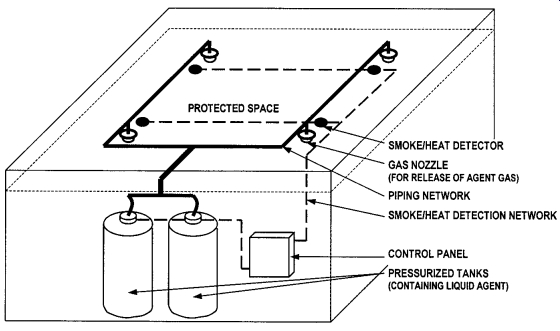
Clean Agent Gas Fire Suppression Systems -- Clean agent gas fire suppression systems discharge as a gas on the surface of combusting materials. A typical system consists of cylinders of a liquid agent under high pressure, heat/smoke detectors, and discharge nozzles connected to a network of pipes. See fgr. 4. Large amounts of heat energy are absorbed from the surface of the burning material, lowering the surface temperature below the ignition point.
Clean agent gases can be released in a building space without leaving residue. When released, they extinguish the fire rapidly but do little harm to building occupants, firefighters, interior contents, and equipment. Typical installations often protected by clean agent gas fire suppression include art and historical collections, computer rooms, data processing centers, telecommunications centers, telephone switching rooms, electrical switchgear and transformer closets, vaults, tape storage areas, and raised floor spaces.
Halogenated hydrocarbons, known as halons, have been used in clean agent gas fire suppression systems for decades.
The most commonly used agent was Halon 1301, an inert gas.
However, because of its damaging effect on the earth's ozone layer, production of Halon 1301 ceased on January 1, 1994.
Halon alternatives include FM-200® (heptafluoropropane), Inergen® (a mixture of three gases: approximately 52% nitro gen, 40% argon, and 8% carbon) and FE-13® (trifluromethane).
These are environmentally friendly with no ozone depletion, no global warming potential, and zero atmospheric lifetime.
Carbon Dioxide (CO2) Fire Suppression Systems Carbon dioxide (CO2) fire suppression systems discharge a CO2 gas that extinguishes fire by displacing oxygen or taking oxygen away from the fire. CO2 is also very cold as it comes out of the extinguisher, so it also cools the fuel. A typical system consists of cylinders of liquid CO2 under high pressure, heat/smoke detectors, and discharge nozzles connected to a network of pipes.
CO2 systems have been an industry standard for many decades and are still the preferred agent in many confined space or tank applications.
The principal problem with CO2 is that it must be used in fairly high concentrations and because high CO2 concentrations deplete much of the oxygen in a space, this type of system can not be used with occupants or other living beings present. As a result, it is usually used in confined areas such as mechanical chases, unventilated areas, and display cases. There are several common application systems that utilize CO2 to extinguish fires in engine compartments, dip tanks, and quench tanks and operations where spilled fuel is a possibility.
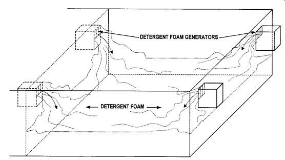
Foam Fire Suppression Systems--- Foam fire suppression systems discharge a high volume of gas-filled bubbles that rapidly fill a space. Foam masses are lighter than water and flammable liquids, and they may be either air or chemical gas bubbles.
They float on the surface of burning liquids to deplete oxygen and smother the fire.
A typical system consists of foam generators, heat/smoke detectors, and a blower system that distributes the foam (see fgr. 5). Other systems discharge foam in a manner similar to a conventional sprinkler system. Foam is very effective on flammable liquid fires and most popular in areas where flammable fuel is likely to be, such as airplane or jet hangars.
Automatic Sprinkler Testing and Maintenance
After installation of an active fire protection system is completed and approved, fire codes generally require a certificate from the contractor indicating that the system was installed in compliance with the code and that all of the required tests were performed. The contractor issuing the certificate must be licensed in installation of fire protection systems. Systems are typically hydrostatically tested at a pressure of at least 200 psi (1380 kPa), which is well above street pressure.
Active fire protection systems must be well maintained to ensure reliability. In particular, systems using water and water based foam are prone to rust deposits that can obstruct sprinkler heads and spray nozzles. Periodic testing and maintenance is essential to ensuring that a fire protection system will work as intended in a fire situation. (See img. 19.) Procedures should be in place to ensure regular maintenance and testing of systems. Maintenance contracts are often placed with a fire protection system contractor. The building operator or manager should keep records of these activities.
fgr. -5 A sketch of a foam fire suppression system.
Influence on Building Design
The presence of an automatic fire sprinkler system and/or smoke control installation influences the allowable size and configuration of a building because it extends the distance an occupant can travel when exiting the building.
Typically, the maximum distance of travel from any point to an exterior exit door, horizontal exit, exit passageway, or an enclosed stairway in a facility, building, or structure not equipped with an automatic fire sprinkler system should not exceed 150 ft.
This distance is extended 200 ft in a facility, building, or structure equipped with an automatic fire sprinkler system installation throughout.
In a single-story factory, warehouse, or airplane hangar, the exit travel distance may typically be increased to 400 ft if the building is equipped with an automatic fire sprinkler system installation throughout and provided with an approved smoke control installation. In an open parking garage, the exit travel distance may be increased to 250 ft with these installations.
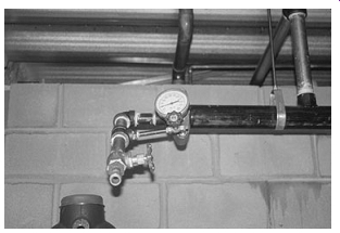
img. 19 A pressure test of a sprinkler system. ( --)
Automatic Sprinkler Systems in Residences
In the United States, almost 80% of all fire fatalities and more than 70% of all fire injuries result from fires starting in residential living rooms, bedrooms, or kitchen areas. Yet, automatic sprinklers are not commonplace in existing single-family residences except at many remote building sites where there is no access to an adequate water supply. A move is underway to re quire automatic sprinklers in new home construction. This movement is based on a ten-year study from 1986 to 1996 in Scottsdale, Arizona, where all new single-family residences were required to be fitted with automatic sprinklers. Sprinklers now protect almost half of the dwellings in this community.
The efforts in Scottsdale resulted in no fire deaths, an 80% reduction of fire injuries and property damage, and a 95% reduction in water usage for fire control. Cost of the sprinkler systems was less than 1/2% of the cost of construction. Homes with residential sprinkler systems received an average discount on insurance of about 10%. As a result of these findings, many communities in the United States have adopted codes or introduced incentive programs for sprinkler installation in one- and two-family dwellings.
fgr. -6 A drawing of a residential sprinkler system.
img. 20 Chlorinated polyvinyl chloride (CPVC) pipe being installed as sprinkler pipe. It will be serving a dwelling unit in a high-rise condominium building. ( --)
Automatic sprinkler systems installed in single-family residences are simplified versions of the systems introduced earlier, usually a variation of the wet-pipe system. A schematic drawing of a residential sprinkler system is shown in fgr. 6. Chlorinated polyvinyl chloride (CPVC) pipe being in stalled as part of a sprinkler system for a dwelling unit in a high rise condominium building is shown in img. 20. Specially designed sprinkler heads spray water on the walls as well as the floor. They are sensitive to both smoldering and rapidly developing fires. Most codes related to systems in residences require automatic sprinklers in all habitable rooms, including the kitchen but excluding small bathrooms and closets. Garages, underfloor crawl spaces, and attic spaces must also be sprinklered.
A residential sprinkler system typically uses a 1/2 in (12.7 mm) orifice, standard sprinkler, with a maximum of 256 ft 2 (23.8 m2 ) coverage, and a 25 gpm (94.6 L/m) flow rate. If the system is not supplied by an adequate public water source, a 250 gal (946.3 L) stored water supply is required to provide a 10 min water supply. Sprinklers are required in living rooms, bedrooms, or kitchen areas, but not required in bathrooms 40 ft 2 (3.7 m2 ) or less, small closets, 24 ft 2 (2.2 m2 ) or less, attics not used as a living space, porches, carports, garages, and foyers.
A multipurpose residential fire sprinkler system com bines the domestic potable cold water system with the residential fire sprinkler system. It uses the cold water piping to serve as a supply for both the domestic fixtures (i.e. sinks, showers, and so on) and the fire sprinklers. Given the likelihood for a reduced amount of pipe and fittings, there is a potential for reduced system cost. Piping products commonly accepted for use in these systems match those used in standard plumbing systems, including copper, CPVC, and cross-linked polyethylene (PEX). A minimum 3/4-in water meter will be required to ensure adequate flow. The two most remote sprinklers in the structure must be designed to operate simultaneously, which usually adds a flow requirement of 16 to 20 gal/min (65 to 75 L/min).
Because multipurpose systems are potable water systems, they eliminate the need for cross-connection control-that is, back flow prevention is not required.
Portable Fire Extinguishers
Portable fire extinguishers can be used to put out most fires in their early stages. They are classified according to their ability to handle specific classes and sizes of fires. Not all fuels are the same, and if a fire extinguisher is used on the wrong type of fuel, it can make matters worse. Labels on extinguishers indicate the class and relative size of fire that they can be expected to handle. A clearly marked fire extinguisher in a cabinet is shown
img. 21 A clearly marked fire extinguisher in a cabinet. ( --)
Types of Portable Fire Extinguishers
There are four classifications of extinguishers.
Class A Extinguishers Class A extinguishers are suitable for use on fires in ordinary combustibles such as wood, paper, rubber, trash, and many plastics, where a quenching-cooling effect is required. The numeral indicates the relative fire extinguishing effectiveness of each unit. Class A extinguishers are rated from 1-A to 40-A. (A discussion on the numbering system follows.) Extinguishers rated for Class A hazards are water, foam, and multipurpose dry chemical types.
Class B Extinguishers
Class B extinguishers are suitable for use on fires in flammable liquids, gases, and greases, where an oxygen-exclusion or flame-interruption effect is essential. Class B extinguishers are rated from 1-B to 640-B. (A discussion follows.) Extinguishers rated for Class B hazards are foam, Halon alternative, and CO2 and multipurpose dry chemical.
Class C Extinguishers
Class C extinguishers are suitable for use on fires involving energized electrical equipment and wiring where the dielectric conductivity of the extinguishing agent is of importance. For example, water-solution extinguishers cannot be used on electrical fires because water conducts electricity and the operator could receive a shock from energized electrical equipment via the water.
Class D Extinguishers
Class D extinguishers are suitable for use on fires in combustible metals such as magnesium, titanium, zirconium, sodium, and potassium. No numeral is used for Class D extinguishers; the relative effectiveness of these extinguishers for use on specific combustible metal fires is de tailed on the extinguisher nameplate.
In addition to the letter designations, Class A and B type extinguishers also carry a numerical rating code. The numbers indicate the level of effectiveness in extinguishing fires, with 10 rated 10 times more effective than 1. A 1-A fire requires 1 1/4 gal (5 L) of water to extinguish. A 2-A fire needs 2 1/2 gal of water (10 L) or twice that of the 1-A fire. So an extinguisher rated 5 A will put out a fire five times as large as one rated 1-A. For Class B extinguishers, the numerical codes are even more complicated, and generally this type of information is of most use to professional firefighters.
Fire extinguishers may contain mixtures of water, but they are also available with gases or dry chemicals. Some of the common types of fire extinguishers are as follows.
Air-Pressurized Water Fire Extinguishers
Air-pressurized water (APW) extinguishers are large, silver tanks filled about two-thirds water, and then pressurized with air. An APW is a giant squirt gun that stands about 2 ft tall and weighs approximately 25 lbs when full. They are designed for Class A fires only (solid combustible materials that are not metals such as wood, paper, cloth, trash, and plastics).
Carbon Dioxide Fire Extinguishers
Carbon dioxide (CO2) fire extinguishers are filled with non flammable carbon dioxide gas under extreme pressure. They are designed for Class B and C fires only (flammable liquid and electrical). CO2 is a gas that extinguishes fire by displacing oxygen. CO2 is also very cold as it comes out of the extinguisher, so it also cools the fuel. CO2 may be ineffective at extinguishing Class A fires because they may not be able to displace enough oxygen to successfully put the fire out. Burning materials may smolder and reignite. CO2 extinguishers are used in laboratories, mechanical rooms, kitchens, and flammable liquid storage areas.
CO2 extinguishers are filled with nonflammable CO2 gas under extreme pressure. A CO2 extinguisher can be recognized by its hard horn and lack of pressure gauge. CO2 cylinders are red and range in size from 5 lbs to 100 lbs or larger. In the larger sizes, the hard horn will be located on the end of a long, flexible hose.
Dry Chemical Fire Extinguishers --- Dry chemical fire extinguishers put out fire by coating the fuel with a thin layer of dust, separating the fuel from oxygen in the air. The powder also works to interrupt the chemical reaction of fire, so these extinguishers are extremely effective at putting out fire. Dry chemical extinguishers come in a variety of types.
"ABC" indicates that they are designed to extinguish Class A, B, and C fires; "BC" indicates that they are designed to extinguish Class B and C fires.
Class ABC fire extinguishers are considered multipurpose.
They are usually filled with ammonium phosphate. They are not ideal for electrical fires because they leave a hard residue that is difficult to remove. Class ABC fire extinguishers are found in a variety of locations. New buildings will have them located in public hallways. They may also be found in laboratories, mechanical rooms, break rooms, chemical storage areas, offices, and vehicles.
ABC extinguishers are red and typically range in size from 5 lbs to 20 lbs. Class BC extinguishers may be located in places such as commercial kitchens or areas with flammable liquids.
Fire Extinguisher Location
Portable fire extinguishers must be strategically situated.
They must be located so the travel distance is not more than 75 ft for Class A and Class D hazard areas, and not more than 50 ft for Class B hazard areas. Extinguishers must be located close to the likely hazards, but not so close that they would be damaged/isolated by the fire. If possible, they should be located along normal paths of egress from the building. Where highly combustible material is stored in small rooms or en closed space, extinguishers should be located outside the door and never inside where they might become inaccessible.
Extinguishers must not be blocked or hidden by stock, material, or machines. They should be located or hung where they will not be damaged by trucks, cranes, and harmful operations, or corroded by chemical processes, and where they will not obstruct aisles or injure passers-by. All extinguisher locations should be made conspicuous. For example, if an extinguisher is hung on a large column or post, a distinguishing red band can be painted around the post. Also, large signs can be posted directing attention to extinguishers. Extinguishers should be kept clean and should not be painted in any way that could camouflage them or obscure labels and markings.
Smoke Control Systems
Smoke can cause significant damage to interior spaces and equipment. For example, smoke can corrode electronic equipment, such as printed circuit boards found in computers. By the time heat accumulates at the ceiling and activates heat detectors or sprinkler heads, smoke could have already done damage. As a result, smoke detectors are recommended in spaces containing electronic equipment such as computer rooms and sound booths.
A smoke control system is an engineered system that uses mechanical fans to produce airflows and pressure differences across smoke barriers to limit and direct smoke movement. It is the part of a fire protection system that manages and directs smoke to protect building occupants and property (both the building and its contents). This system can also be used to assist firefighting activities.
A water flow indicator from the automatic sprinkler system or an area smoke detector automatically actuates smoke control systems. In-duct smoke detectors can also be used but only in conjunction with water flow indicators and/or area smoke detectors. They should not be the sole means of activation because they often do not react quickly enough to fires in building spaces.
The concept of zoned smoke control requires a building to be divided into a number of smoke control zones. Physical barriers such as walls, floors, ceilings, and doors separate the zones from each other. In a fire scenario, the spread of smoke from the zone of fire origin (called the smoke zone) to adjacent zones is limited by pressure differences and airflows. Pressure differences across the barriers of the zone of origin can be accomplished by supplying outside air to the other zones, by venting the smoke zone, or by a combination of both.
In large buildings, each floor is typically a separate zone.
However, the system can also be designed so that a floor can have a number of zones, or a single zone can consist of more than one level.
Prev: Passive Fire
Protection
Next: Fire Detection and Alarm
Systems